Utility vacuum

a vacuum and utility technology, applied in the field of vacuums, can solve the problems of the common storage or holding of dirt and debris by the vacuum, the emptying of the dirt cavity, and the tendency of dirt and debris to adhere to the sides of the housing, etc., to achieve convenient storage, small footprint, and stable operation.

Inactive Publication Date: 2007-10-30
BLACK & DECKER INC
View PDF185 Cites 32 Cited by
  • Summary
  • Abstract
  • Description
  • Claims
  • Application Information

AI Technical Summary

Benefits of technology

[0010]In one form, the present teaching provide a utility vacuum that is stable in operation but which has a relatively small footprint that renders the utility vacuum easier to store. The present invention employs legs for mounting a set of wheels to the canister of utility vacuum. The legs are movable between an extended position, which provides relatively stable operation of the utility vacuum, and a retracted position, which reduces the footprint of the utility vacuum so that it is easier to store.
[0011]In another form, the present teachings provide a utility vacuum that is relatively less messy to operate. In one aspect, the utility vacuum is configured to employ a disposable bag or removable and reusable container for the collection of dirt and debris that are drawn into the utility vacuum. Construction in this manner reduces or eliminates contact between the user of the utility vacuum and the dirt and debris. In another aspect, the utility vacuum is configured to employ a prefilter screen that is disposed between the primary filter and the cavity in the utility vacuum that holds the dirt and debris. The prefilter screen reduces the dirt and debris that are deposited onto the powerhead assembly of the utility vacuum so that the user is exposed to less dirt and debris when it is necessary to remove the powerhead assembly (for the emptying of the canister housing).
[0012]In a further form, the present teachings provide a utility vacuum with improved ergonomics. In one aspect, the present teachings provide a utility vacuum with a handle that may be extended so that the user does not have to lift the entire unit or stoop to push or pull the unit when the utility vacuum is to be transported. In another aspect of the invention, the utility vacuum is further provided with a set of wheels that fully carry the weight of the utility vacuum (and its contents) when the handle assembly is employed.
[0013]In another form, the present teachings provide a utility vacuum with an accessory apron for the convenient storage and transport of tools and accessories that are employed with the utility vacuum.

Problems solved by technology

While the known utility vacuums work for their intended purpose, we have noted several drawbacks with their configurations.
One such drawback concerns the manner in which dirt and debris are commonly stored or held by the utility vacuum.
Another drawback with the known utility vacuums concerns the emptying of the dirt cavity.
Furthermore, if the dirt and debris are moist or if water is introduced to the dirt cavity, the dirt and debris tends to adhere to the sides of the housing.
Yet another drawback concerns the overall size and portability of the known utility vacuums.
The known utility vacuums tend to either utilize a relatively large footprint, which renders the utility vacuum stable during use but relatively difficult to store, or a relatively small footprint, which renders the utility vacuum relatively easy to store but relatively unstable (i.e., tip-able) during use.
Furthermore, the known configurations typically do not accommodate the moving of the utility vacuum over relatively long-distances.
A further drawback of the known configuration concerns the storage of tools and accessories that are commonly employed with the utility vacuum.
Although pockets or the like could alternatively be formed into the exterior surface of the housing for retaining the tools and accessories, this approach would tend to adversely effect tooling costs (due to the increased complexity of the tool) and would also render the cleaning of the dirt cavity more difficult due to the contouring of inside surface of the housing.

Method used


Image

  • Utility vacuum
  • Utility vacuum
  • Utility vacuum

Examples


Embodiment Construction

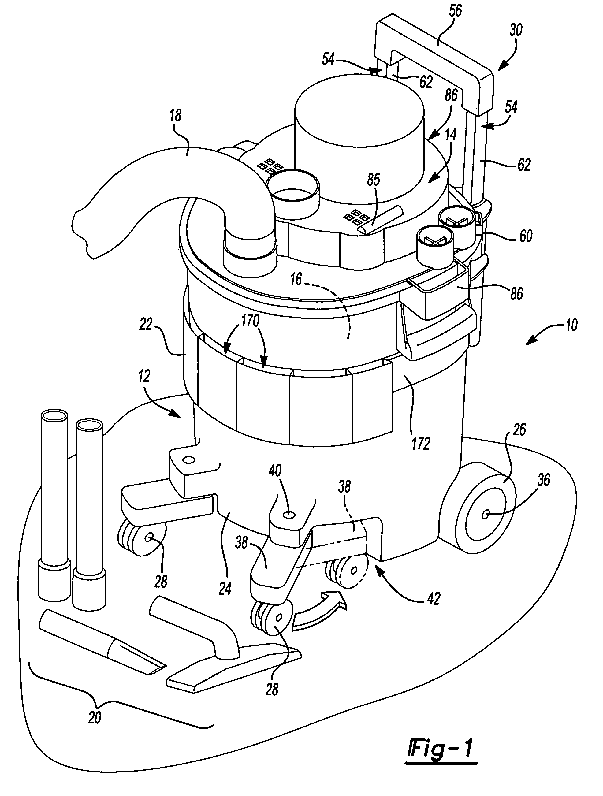
[0036]With reference to FIG. 1 of the drawings, a hand-portable wet / dry vacuum constructed in accordance with the teachings of the present invention is generally indicated by reference numeral 10. The vacuum 10 is shown to include a canister assembly 12, a powerhead assembly 14, a filter system 16, a hose assembly 18, a plurality of conventional hose-end attachments 20 and an accessory apron 22.

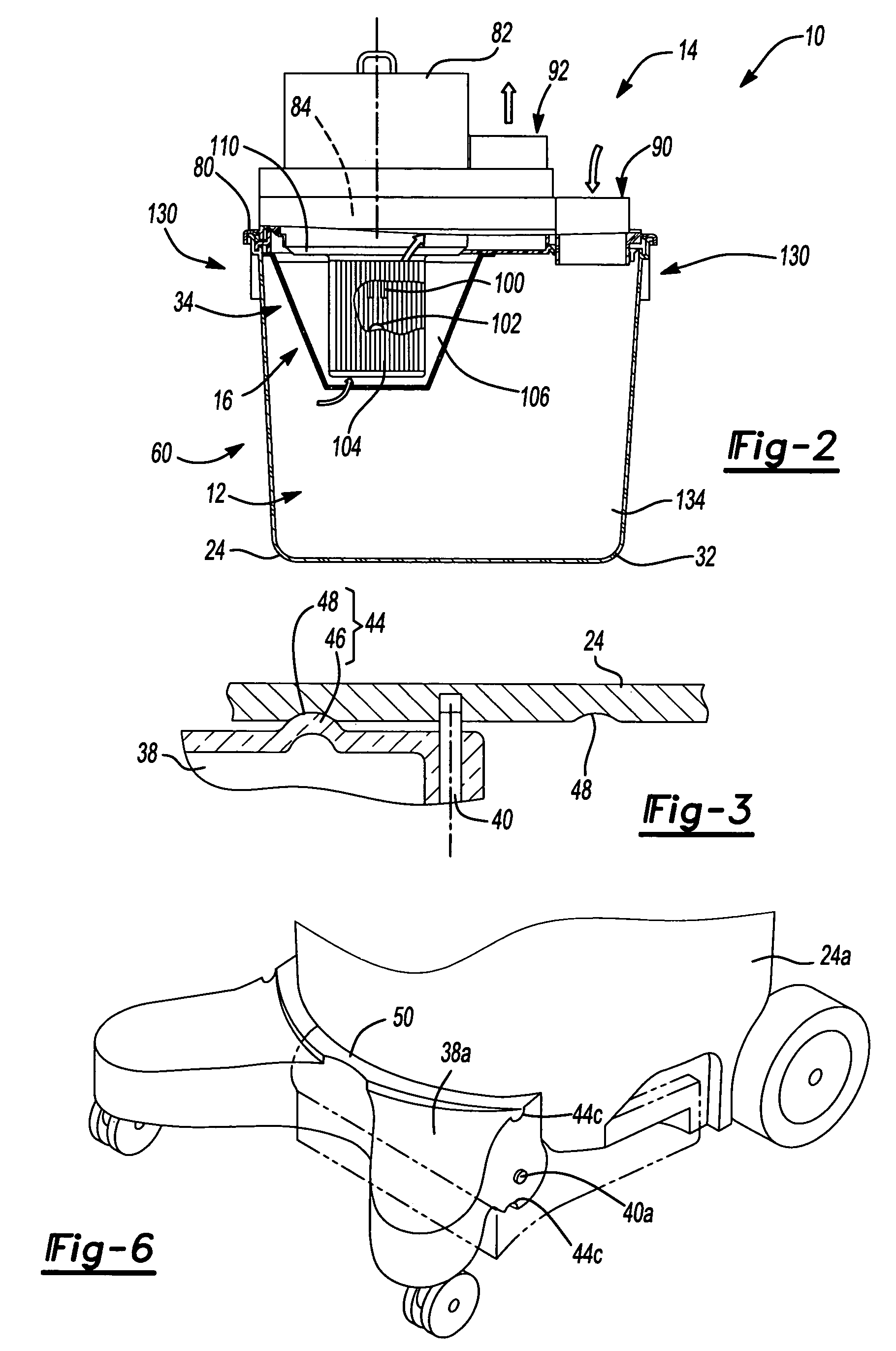
[0037]With additional reference to FIG. 2, the canister assembly 12 includes a canister housing 24, a first set of wheels 26, a second set of wheels 28 and a handle assembly 30. The canister housing 24 is cup or pail like in shape so as to define a central cavity 32 with a generally open top 34.

[0038]In the example illustrated, an axle 36 is employed to couple the first set of wheels 26 to the canister housing 24. More specifically, the axle 36 extends through and is rotatably supported by a portion of the canister housing 24 and the first wheels 26 are coupled to the opposite ends of the axl...


PUM

PropertyMeasurementUnit
angleaaaaaaaaaa
vacuumaaaaaaaaaa
areaaaaaaaaaaa

Abstract

A utility vacuum that may be configured to employ a disposable bag or removable and reusable container for the collection of dirt and debris that are drawn into the utility vacuum. The utility vacuum may employ one or more movable legs that are movable between an extended position, which provides relatively stable operation of the utility vacuum, and a retracted position, which reduces the footprint of the utility vacuum so that it is easier to store.

Description

[0001]This application claims the benefit of U.S. Provisional Application No. 60 / 485,953 filed Jul. 10, 2003.FIELD OF THE INVENTION[0002]The present invention generally relates to vacuum appliances and more particularly to a portable wet / dry utility vacuum having improved convenience and performance.BACKGROUND OF THE INVENTION[0003]It is relatively commonplace to find two types of vacuums in modern households: one that is suited for vacuuming floors and carpets, such as an upright vacuum or a canister-type vacuum, and another for relatively heavy-duty cleaning tasks, such as a wet / dry vacuum.[0004]Utility vacuums, also known as wet / dry vacuums, are commonly employed in the basements, garages and / or work shops of modern households for relatively heavy-duty cleaning tasks. While the known utility vacuums work for their intended purpose, we have noted several drawbacks with their configurations.[0005]One such drawback concerns the manner in which dirt and debris are commonly stored or ...

Claims


Application Information

Patent Timeline
Patent Type & Authority Patents(United States)
IPC IPC(8): A47L9/00A47L5/36A47L7/00A47L9/02A47L9/10A47L9/14A47L9/32
CPCA47L5/225A47L5/365A47L7/0028A47L7/0038A47L7/0042A47L9/0009A47L9/0045A47L9/009A47L9/02A47L9/1418A47L9/327A47L9/0027Y10S55/03
Inventor MARSHALL, JAMES D.SERGYEYENKO, OLEKSIY P.SMITH, RAY T.NAWROZKI, DAMONBALDWIN, MICHELLE M.ROSA, RICHARD P.MENG, ANDREW E.
Owner BLACK & DECKER INC
Why Eureka
Try Eureka