Power working machine

a working machine and working handle technology, applied in the direction of wing knobs, metal sawing accessories, furniture parts, etc., can solve the problems of cumbersome and complicated operation of the operating handle by the human operator, and achieve the effects of enhancing the workability simplifying the rotating operation of the operating handle, and increasing reliability

Inactive Publication Date: 2007-10-30
HONDA MOTOR CO LTD
View PDF3 Cites 30 Cited by
  • Summary
  • Abstract
  • Description
  • Claims
  • Application Information

AI Technical Summary

Benefits of technology

[0006]In view of the foregoing prior art problems, it is an object of the present invention to provide an improved power working machine which allows the human operator to rotate the operating handle as desired with simple operation and which also allows the human operator to operate the throttle lever and operating handle with increased reliability.

Problems solved by technology

However, with the conventional power working machine 200, the human operator's rotating and locking operation of the operating handle 202 is very cumbersome and complicated because the human operator has to first rotate the handle 202 through a desired rotational angle relative to the machine body 201, disengage the throttle lock lever 204 from the throttle lever 203 and then grip the throttle lever 203 to thereby press the lock member 205 against the machine body 201 so as to lock the handle 202.

Method used


Image

  • Power working machine
  • Power working machine
  • Power working machine

Examples


first embodiment

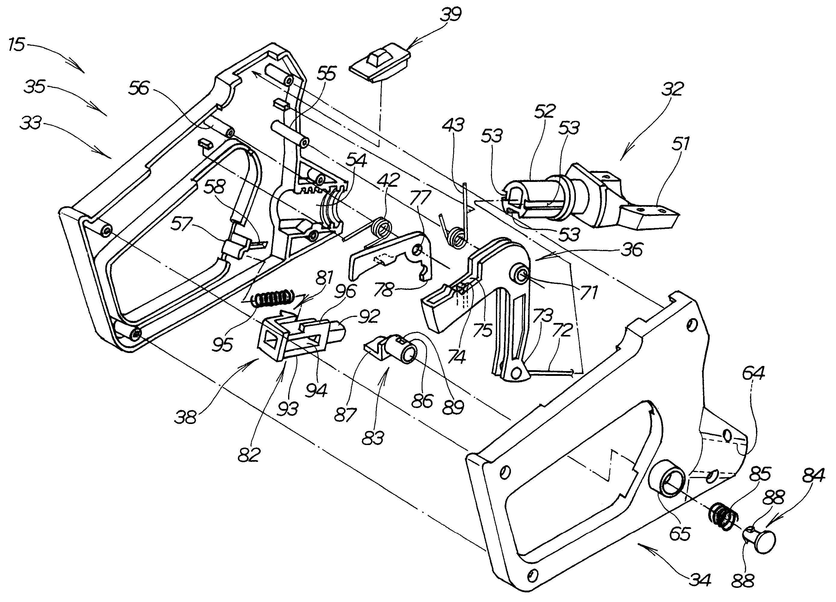
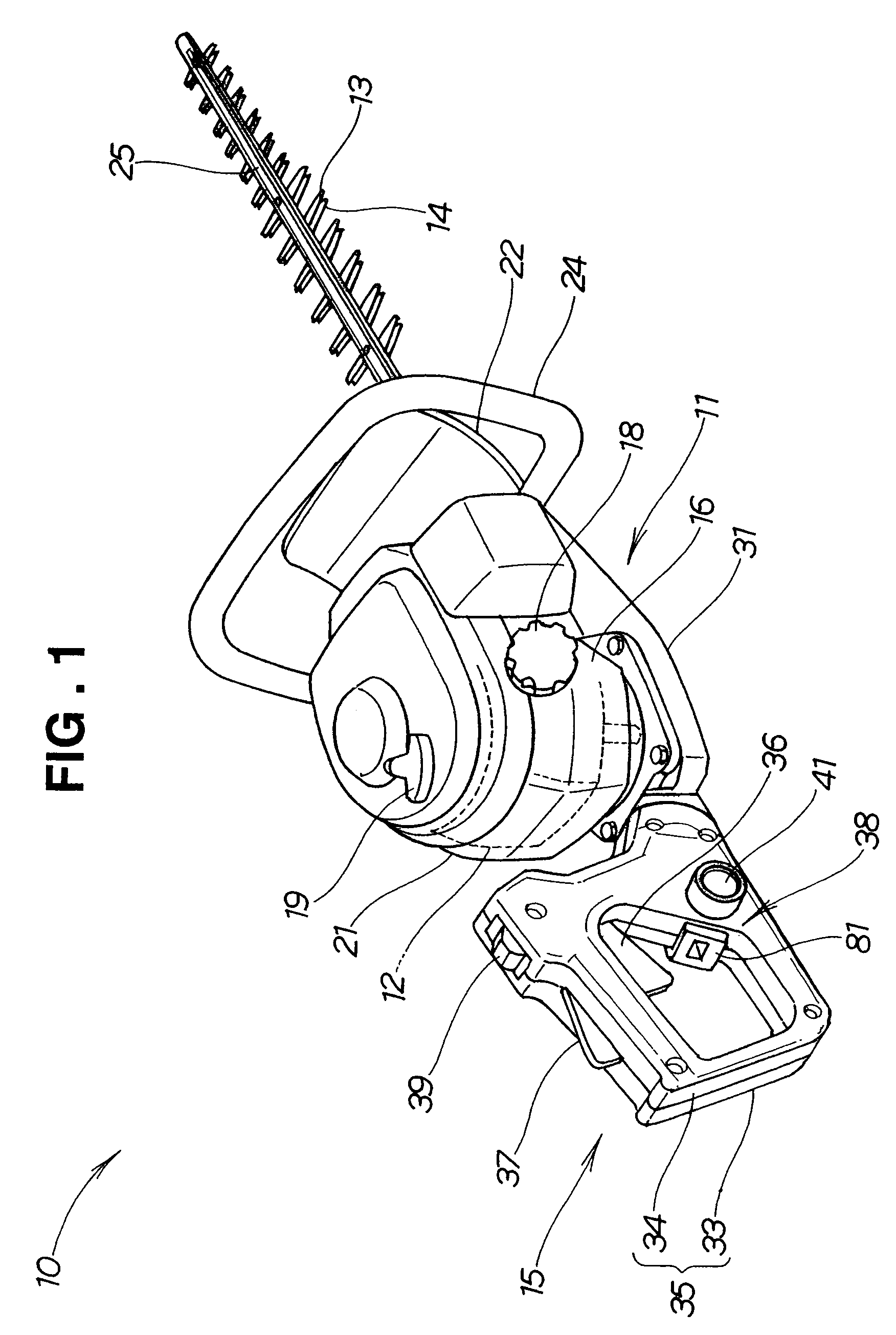
[0039]Initial reference is made to FIG. 1 illustrating in perspective a power working machine in accordance with the present invention. The power working machine 10 of FIG. 1 is specifically constructed as a “hedge trimmer”, where a rotation force output from a drive source 12, such as an engine, is converted, after appropriate speed reduction, into reciprocating movement and the resultant reciprocating movement is delivered to a work implement comprising cutting means in the form of upper and lower trimming blades 13 and 14 to trim a hedge. Also, in the power working machine 10, an operating handle 15 can be turned or rotated relative to the machine body, as necessary, in accordance with a changing operating posture or position of a human operator (user) when trimming an upper or side surface of a hedge.

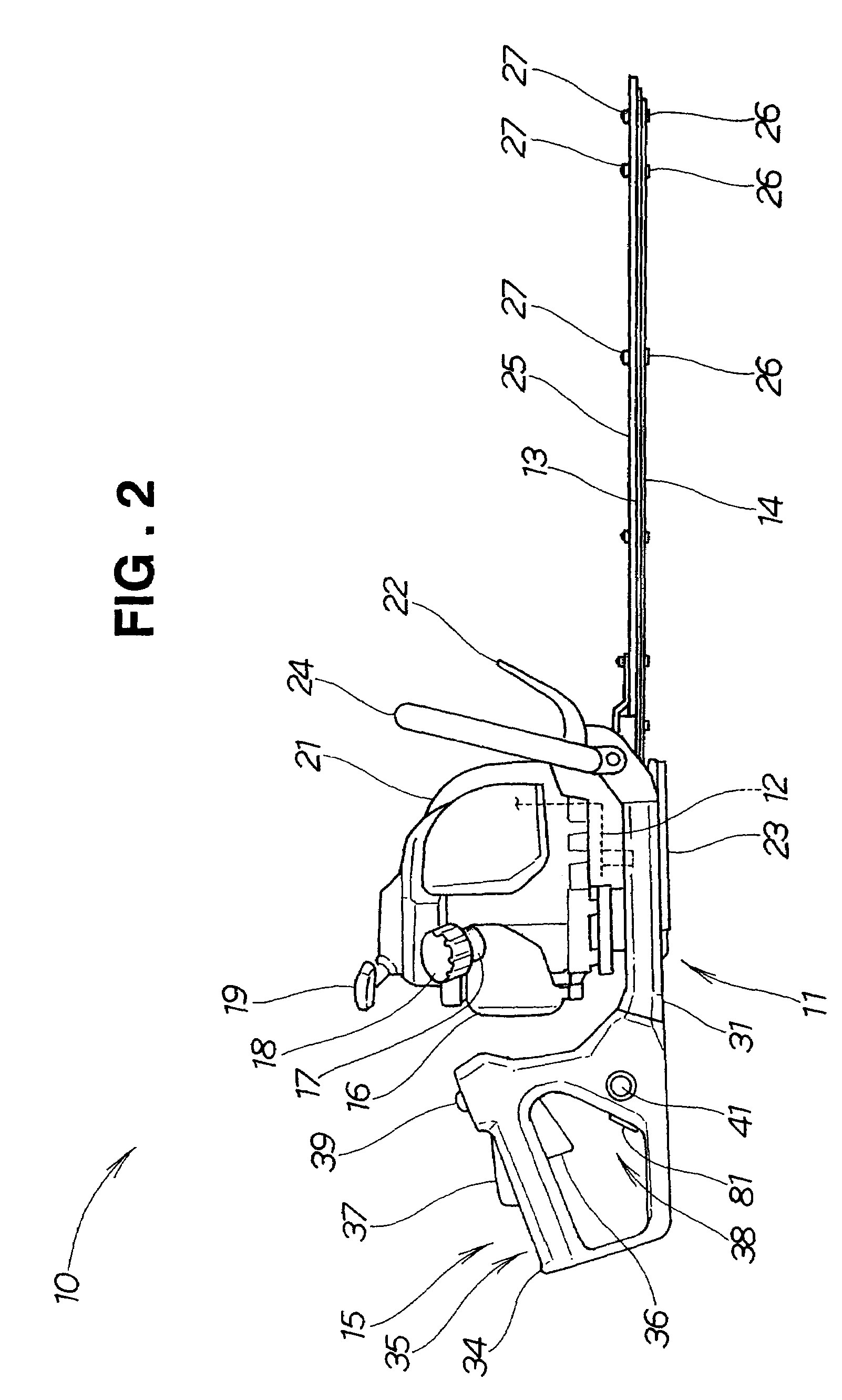
[0040]FIG. 2 is a side view of the power working machine 10 of the invention. As shown, the power working machine (hedge trimmer) 10 includes the drive source 12 mounted generally c...

second embodiment

[0075]FIG. 12 is a perspective view of a power working machine in accordance with another or second embodiment of the present invention. The power working machine 100 of FIG. 12 is specifically constructed as a “hedge trimmer”, where a rotation force output from a drive source 112, such as an engine, is converted, after appropriate speed reduction, into reciprocating movement and the resultant reciprocating movement is delivered to upper and lower trimming blades 113 and 114 to trim a hedge. Also, in the power working machine 100, an operating handle 115 can be turned or rotated relative to the machine body, as necessary, in accordance with a changing operating posture or position of a human operator (user) when trimming an upper or side surface of a hedge.

[0076]FIG. 13 is a side view of the second embodiment of the power working machine 100 shown in FIG. 2. As shown, the power working machine 100 includes the drive source 112 mounted generally centrally on the machine body 111, a f...

case member 131

[0077]Case member 131 is mounted on the machine body 111 and accommodates therein mechanisms for reducing the rotation speed of the drive source 112 and for converting the speed-reduced rotation force into reciprocating movement, a shaft section 132 is provided on the case member 31, and the operating handle 115 is connected to the shaft section 132 for rotation relative to the machine body 111.

[0078]FIG. 14 is a partly-sectional side view of the operating handle 115 of the power working machine 100, which particularly shows one of left and right handle halves 133 and 134 (see FIG. 12); only the left handle half 133 is shown in FIG. 14 with the right handle half 134 removed.

[0079]The operating handle 115 includes a handle body 135 composed of the left and right handle haves 133 and 134, a throttle lever 136 rotatably connected to the handle body 135 for adjusting the output power of the drive source 112 (see FIG. 13), and a throttle lock lever 137 pivotally connected to the handle b...


PUM

PropertyMeasurementUnit
workabilityaaaaaaaaaa
poweraaaaaaaaaa
rotational angleaaaaaaaaaa

Abstract

A power working machine has a machine body, a drive source mounted on the machine body for driving a work implement connected to the machine body, and an operating handle mounted on the machine body for undergoing rotation relative to the machine body. A throttle lever is mounted on the operating handle for undergoing pivotal movement to adjust an output of the drive source. A lock mechanism is mounted on the operating handle for locking the operating handle at a preselected rotational angular position relative to the machine body. A lock cancellation lever is mounted on the operating handle for unlocking the lock mechanism to thereby permit rotational movement of the operating handle relative to the machine body. A stopper section is mounted on the operating handle for permitting operation of the lock mechanism while preventing pivotal movement of the throttle lever and for preventing operation of the lock mechanism while permitting pivotal movement of the throttle lever.

Description

FIELD OF THE INVENTION[0001]The present invention relates to a power working machine which can trim an upper surface, side surface, etc. of a hedge with an enhanced workability by allowing a human operator to rotate its operating handle in accordance with desired trimming positions.BACKGROUND OF THE INVENTION[0002]Examples of power working machines in practical use today include those in which an operating handle is rotatably mounted on a machine body, a throttle lever is mounted on the operating handle for adjustment of an output power from a drive source, such as an engine, and a throttle lock lever is also mounted on the operating handle for locking the throttle lever. For practical use, it has been only necessary that the power working machines include, in addition to the throttle lever and throttle lock lever, a lock mechanism provided on the machine body for locking the operating handle at a desired rotational angle relative to the machine body and an operation lever dock-canc...

Claims


Application Information

Patent Timeline
Patent Type & Authority Patents(United States)
IPC IPC(8): B27B19/02A01G3/04A01G3/053B23D51/01
CPCA01G3/053Y10T74/18056Y10T16/44Y10S16/90
Inventor SASAKI, HIDESHIHIRATSUNA, KENJIRO
Owner HONDA MOTOR CO LTD
Why Eureka
Try Eureka