Bicycle generator hub
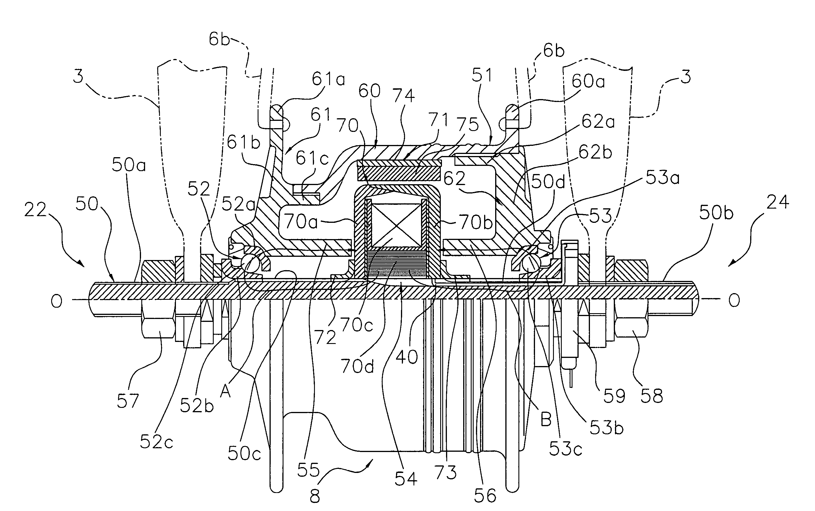
a generator hub and bicycle technology, applied in bicycle equipment, optical signals, transportation and packaging, etc., can solve the problem of large amount of magnetic flux passing through the coil, and achieve the effect of reducing costs and maximizing power generation efficiency
- Summary
- Abstract
- Description
- Claims
- Application Information
AI Technical Summary
Benefits of technology
Problems solved by technology
Method used
Image
Examples
second embodiment
[0066]Referring now to FIG. 6, a bicycle generator hub 208 in accordance with a second embodiment will now be explained. In view of the similarity between the first and second embodiments, the parts of the second embodiment that are identical to the parts of the first embodiment will be given the same reference numerals as the parts of the first embodiment. Moreover, the descriptions of the parts of the second embodiment that are identical to the parts of the first embodiment may be omitted for the sake of brevity.
[0067]The bicycle generator hub 208 is essentially the same as in the first embodiment except that the first and second magnetic flux recirculation members 255 and 256 are not directly attached to the first and second cap members 261 and 262. Referring to FIG. 6, the first and second magnetic flux recirculation members 255 and 256 are annular members that are threaded onto the large-diameter thread 50c of the hub shaft 50. The coil 70 is located on the hub shaft 50 between...
third embodiment
[0068]Referring now to FIG. 7, a bicycle generator hub 308 in accordance with a third embodiment will now be explained. In view of the similarity between the first and third embodiments, the parts of the third embodiment that are identical to the parts of the first embodiment will be given the same reference numerals as the parts of the first embodiment. Moreover, the descriptions of the parts of the third embodiment that are identical to the parts of the first embodiment may be omitted for the sake of brevity.
[0069]The bicycle generator hub 308 is essentially the same as in the first embodiment except that the first and second magnetic flux recirculation members 355 and 356 contact the coil 70 and are proximate to the first and second cap members 361 and 362. Specifically, as is illustrated in FIG. 7, each of the first and second magnetic flux recirculation members 355 and 356 has a first end portion that contacts the coil 70 and a second end portion that is disposed proximate to t...
fourth embodiment
[0071]Referring now to FIG. 8, a bicycle generator hub 408 in accordance with a fourth embodiment will now be explained. In view of the similarity between the first and fourth embodiments, the parts of the fourth embodiment that are identical to the parts of the first embodiment will be given the same reference numerals as the parts of the first embodiment. Moreover, the descriptions of the parts of the fourth embodiment that are identical to the parts of the first embodiment may be omitted for the sake of brevity.
[0072]The bicycle generator hub 408 is essentially the same as in the first embodiment except that the first and second magnetic flux recirculation members 455 and 456 contact the coil 70 and are proximate to the hub shaft 50. Specifically, as is illustrated in FIG. 8, each of the first and second magnetic flux recirculation members 455 and 456 has a first end portion that contacts the coil 70 and a second end portion that is disposed proximate to the hub shaft 50. The coi...
PUM
 Abstract
Description
Claims
Application Information
 - R&D
- Intellectual Property
- Life Sciences
- Materials
- Tech Scout
- Unparalleled Data Quality
- Higher Quality Content
- 60% Fewer Hallucinations
Browse by: Latest US Patents, China's latest patents, Technical Efficacy Thesaurus, Application Domain, Technology Topic, Popular Technical Reports.
© 2025 PatSnap. All rights reserved.Legal|Privacy policy|Modern Slavery Act Transparency Statement|Sitemap|About US| Contact US: help@patsnap.com


