Electroluminescent display device

a display device and electroluminescent technology, applied in the direction of static indicating devices, identification means, instruments, etc., can solve the problems that the organic el display device has not been applied to touch panels used with the finger or pen-type pointing devices, and achieve the effects of reducing the number of components of the display device, improving accuracy in the detection of x and y coordinates, and miniaturizing the display devi

Inactive Publication Date: 2007-10-30
SANYO ELECTRIC CO LTD
View PDF15 Cites 17 Cited by
  • Summary
  • Abstract
  • Description
  • Claims
  • Application Information

AI Technical Summary

Benefits of technology

[0008]This invention provides an organic EL display device having a touch panel function, and is directed to improving accuracy in positional detection on a display portion of such an organic EL display device. An organic EL display device of the invention is formed with a display portion by disposing display pixels each having a display organic EL element in a matrix. A first light source portion having a plurality of light source organic EL elements is provided, being disposed along a first side of the display portion. A first light detecting portion having a plurality of detection light sensors is provided, being disposed along a side opposite from the first side. Similarly, a second light source portion having a plurality of light source organic EL elements is provided, being disposed along a second side of the display portion. A second light detecting portion having a plurality of detection light sensors is provided, being disposed along a side opposite from the second side.
[0010]In this invention, an organic EL display device having a touch panel function can be realized in one display panel. This reduces the number of components in the display device, and the display device can be miniaturized. Furthermore, detection of a x coordinate and a y coordinate of a point P on the display portion is performed by comparing outputs of the detection light sensors and outputs of the reference light sensors in the light detecting portions by the comparators so that accuracy in the detection of the x and y coordinates improves.

Problems solved by technology

However, the organic EL display device has not been applied to touch panels used with the finger or the pen-type pointing device.

Method used


Image

  • Electroluminescent display device
  • Electroluminescent display device
  • Electroluminescent display device

Examples


Embodiment Construction

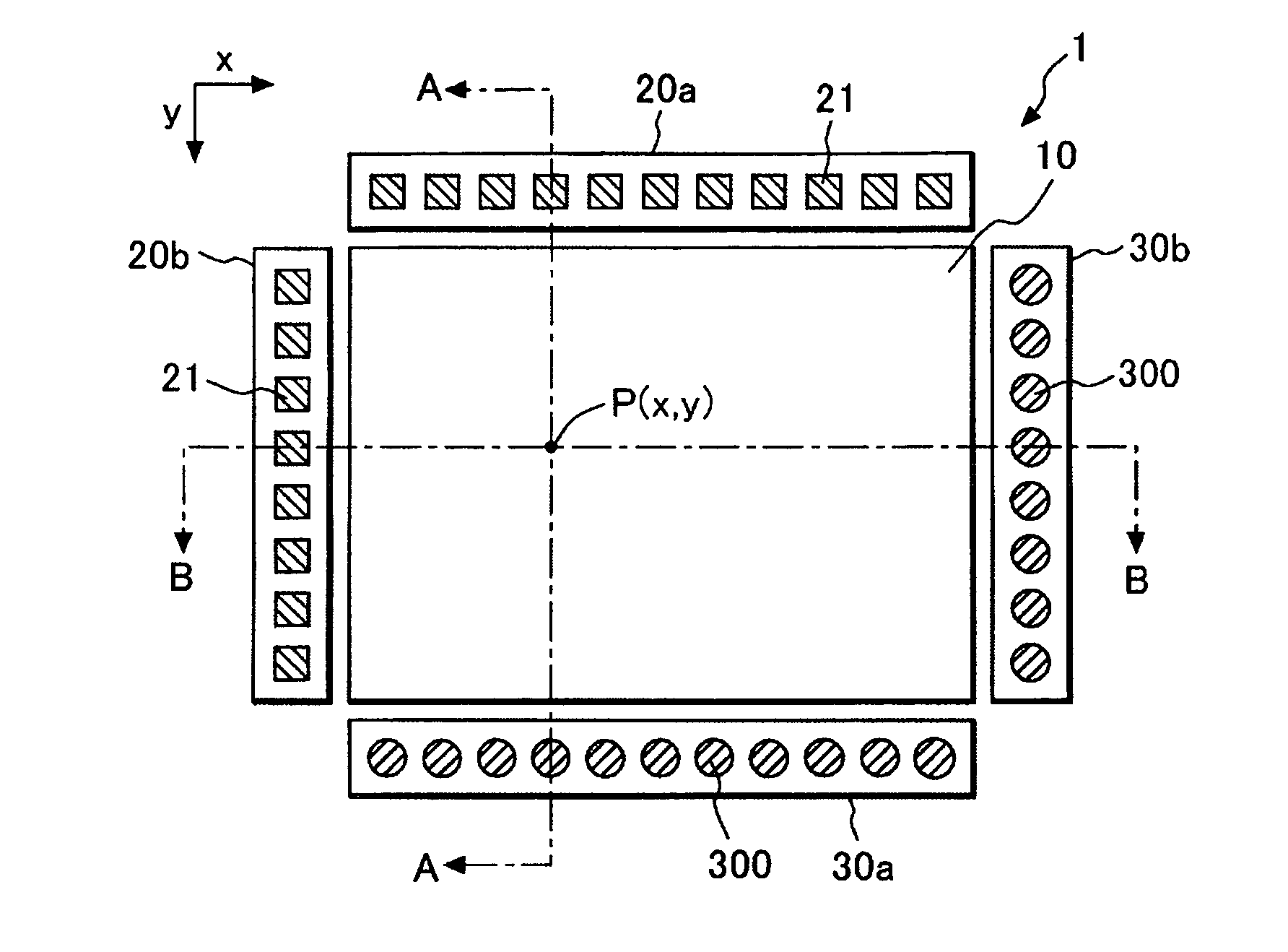
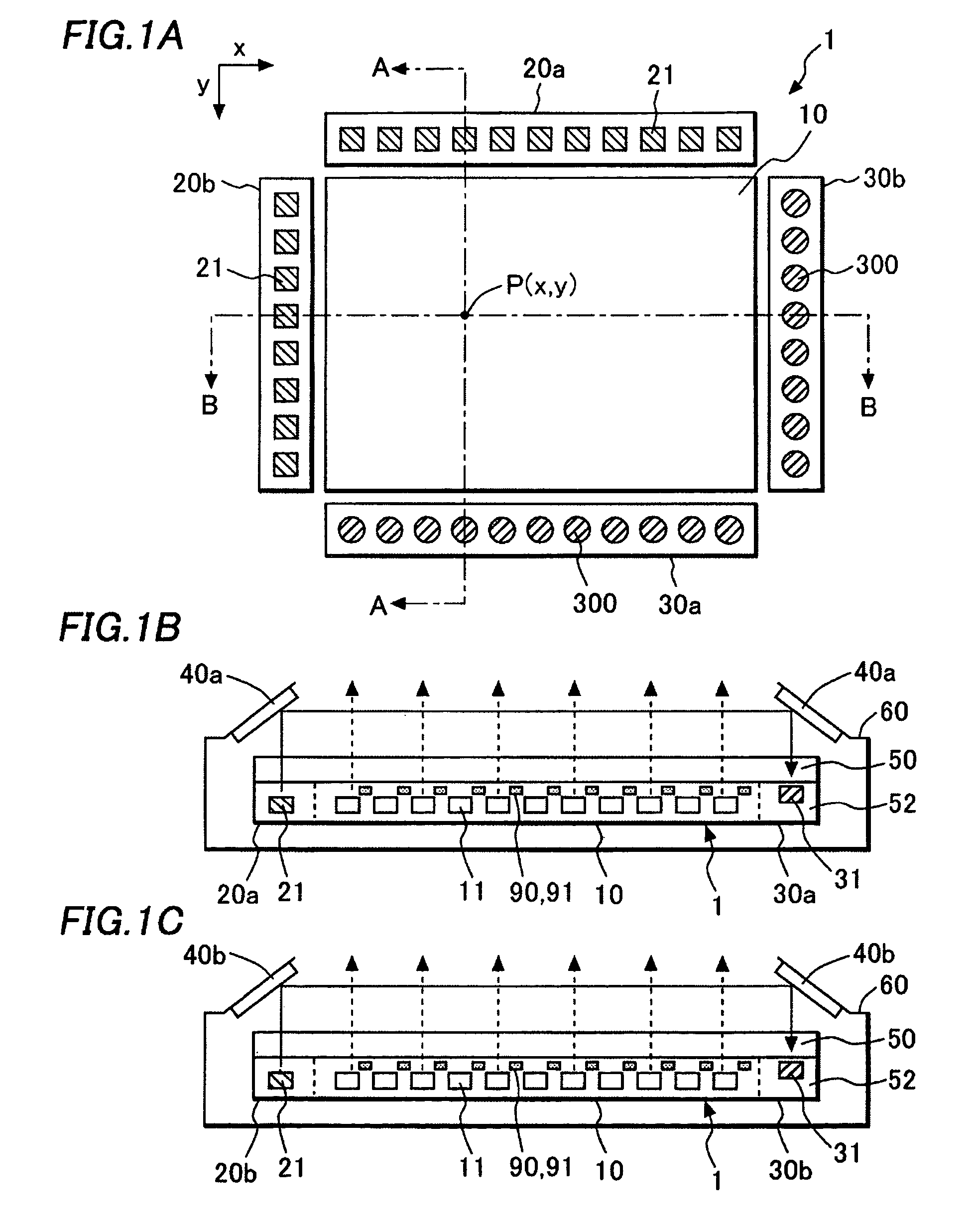
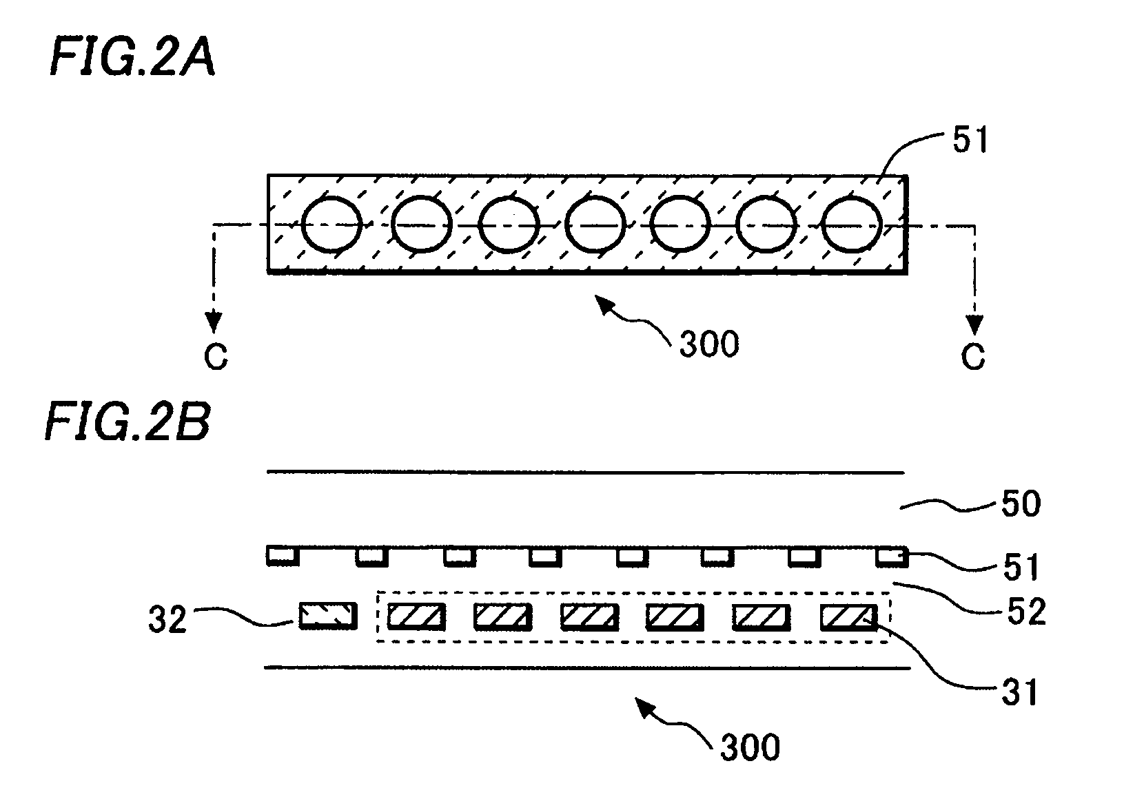
[0017]A structure of an organic EL display device of one embodiment of the invention will be described with reference to the drawings. FIG. 1A is a plan view of the organic EL display device of this embodiment. FIG. 1B is a cross-sectional view of FIG. 1A along line A-A. FIG. 1C is a cross-sectional view of FIG. 1A along line B-B. FIG. 2A shows an upper surface of one of blocks 300 in first and second light detecting portions 30a and 30b, and FIG. 2B is a cross-sectional view of FIG. 2A along line C-C. A block 300 of the light detecting portions 30a and 30b is a segment of a corresponding light detecting portion that includes a plurality of detection light sensors 31 and a reference light sensor 32, as explained below. FIG. 4 is an equivalent circuit diagram of one of blocks 300 in the first and second light detecting portions 30a and 30b.

[0018]In this embodiment, in a display portion 10 of a display panel 1, a plurality of display pixels (not shown) is disposed in a matrix. Each o...


PUM


Abstract

An organic electroluminescent (EL) display device has a touch panel function and includes a display panel that has first and second light sources disposed along sides of the display portion and first and second light detecting portions disposed on sides of the display portion opposite the light sources. The display device includes a plurality of organic EL display elements disposed in a matrix on the display portion and a plurality of organic EL light source elements disposed in a row in each of the light source portions. The light detecting portions include a plurality of detection light sensors and a reference light sensor disposed in a row in each of the light detecting portions. The display device also includes a comparator that compares an output of the detection light sensors with the output of the reference light sensor.

Description

CROSS-REFERENCE OF THE INVENTION[0001]This invention is based on Japanese Patent Application No. 2003-340650, the content of which is incorporated by reference in its entirety.BACKGROUND OF THE INVENTION[0002]1. Field of the Invention[0003]This invention relates to an electroluminescent display device, particularly to an electroluminescent display device having a touch panel function.[0004]2. Description of the Related Art[0005]In recent years, organic electroluminescent (hereafter, referred to as EL) display devices using EL elements have been receiving attention as a display device substituting for a CRT or an LCD. Particularly, organic EL display devices having thin film transistors (hereafter, referred to as TFTs) as switching elements for driving the organic EL elements have been developed.[0006]The LCD has a wide range of applications, for example, from displays for cellular phones to those for personal digital assistants. Furthermore, a touch panel used with a finger or a pen...

Claims


Application Information

Patent Timeline
Patent Type & Authority Patents(United States)
IPC IPC(8): G09G3/30G06F3/03H05B33/12G06F3/033G06F3/041G06F3/042G09F9/00G09G3/10H01L51/50H05B33/14
CPCG06F3/0421G06F3/03
Inventor MATSUMOTO, SHOICHIRO
Owner SANYO ELECTRIC CO LTD
Why Eureka
Try Eureka