System and tracker for tracking an object, and related methods

a tracking system and object technology, applied in the field of tracking apparatus, can solve problems such as the loss of tracking solutions, and achieve the effects of facilitating installation, and enhancing the detection of a trackable body

Active Publication Date: 2007-10-30
BEST MEDICAL INT
View PDF23 Cites 66 Cited by
  • Summary
  • Abstract
  • Description
  • Claims
  • Application Information

AI Technical Summary

Benefits of technology

[0014]In view of the foregoing, embodiments of the present invention advantageously provide a system, tracker, and methods related to use of a tracker that provides a user the ability to track both the three-dimensional position and the orientation of a movable object over substantially all possible object orientations without significant occlusion. Advantageously, embodiments of the present invention also provide a tracker that is size scalable in order to meet requirements of the movable object and to control the accuracy of the tracking solution. Advantageously, embodiments of the present invention also provide a geometric indicator or emitter design which forms a plurality of preferably dissimilar geometric figures composed of three or more indicators or emitters preferably in the form of retro-reflective spheres that are readily distinguishable by an optical detector or camera system. Advantageously, embodiments of the present invention also provide flanges and other “obfuscating” structures that occlude or prevent coincident alignment of specific optical indicators from view by the optical detector or camera system. This prevents indicators which comprise one geometric figure from becoming juxtaposed or optically coincident with indicators which form another geometric figure, which would result in the indicators being unusable to the optical detector or camera system, and thus loss of a tracking solution. Advantageously, embodiments of the present invention incorporate a mechanical quick disconnect to allow ready removal from the movable object being tracked while still providing positioning functionality and which compels the tracker into the correct mounting position on the movable object, to prevent use of the tracker in an incorrect state.

Problems solved by technology

This prevents indicators which comprise one geometric figure from becoming juxtaposed or optically coincident with indicators which form another geometric figure, which would result in the indicators being unusable to the optical detector or camera system, and thus loss of a tracking solution.

Method used


Image

  • System and tracker for tracking an object, and related methods
  • System and tracker for tracking an object, and related methods
  • System and tracker for tracking an object, and related methods

Examples


Embodiment Construction

[0045]The present invention will now be described more fully hereinafter with reference to the accompanying drawings, which illustrate embodiments of the invention. This invention may, however, be embodied in many different forms and should not be construed as limited to the illustrated embodiments set forth herein. Rather, these embodiments are provided so that this disclosure will be thorough and complete, and will fully convey the scope of the invention to those skilled in the art. Like numbers refer to like elements throughout. Prime notation, if used, indicates similar elements in alternative embodiments. Note, the term “indicator” as used herein refers to either active or passive emitters including but not limited to optically retro-reflective spheres.

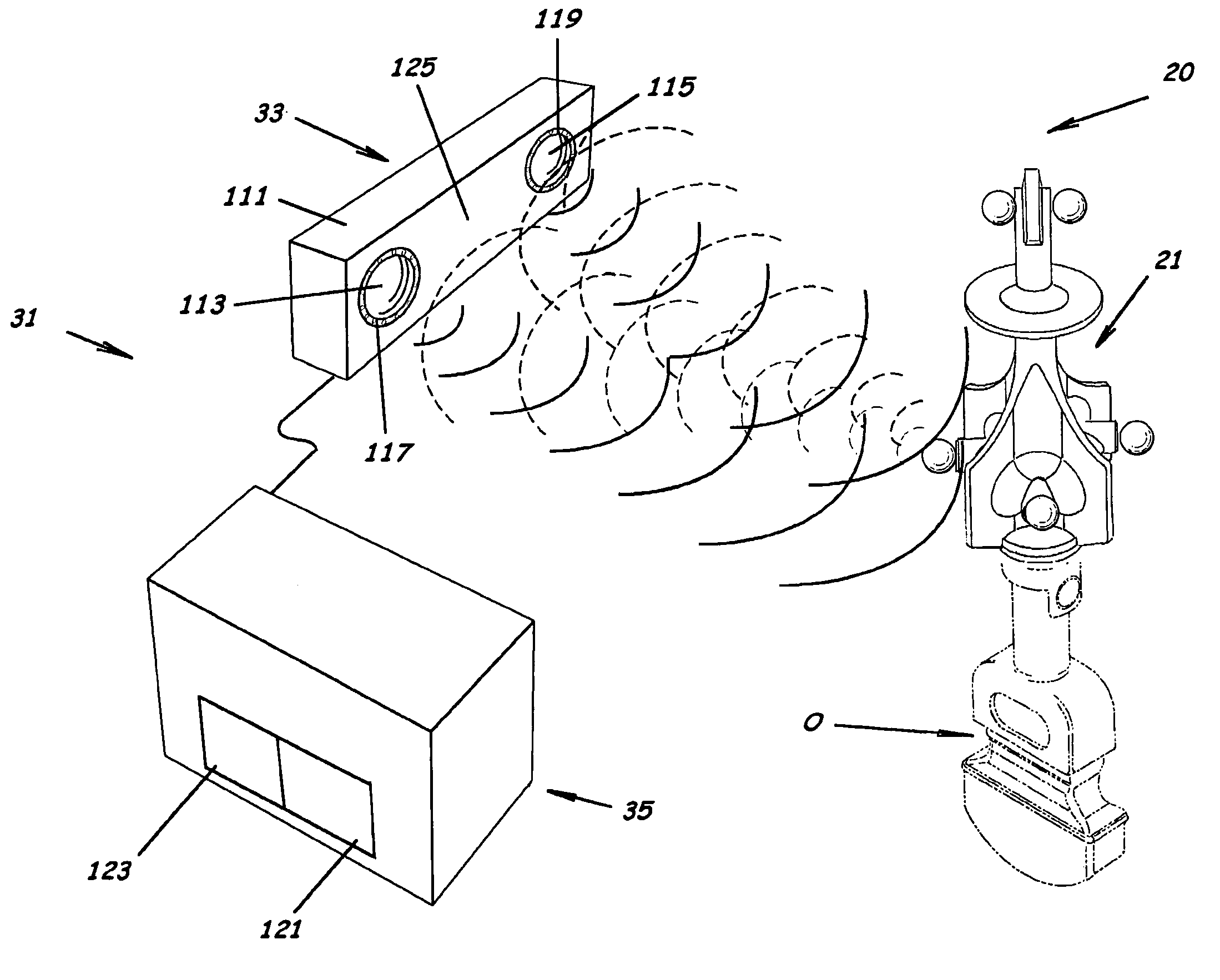
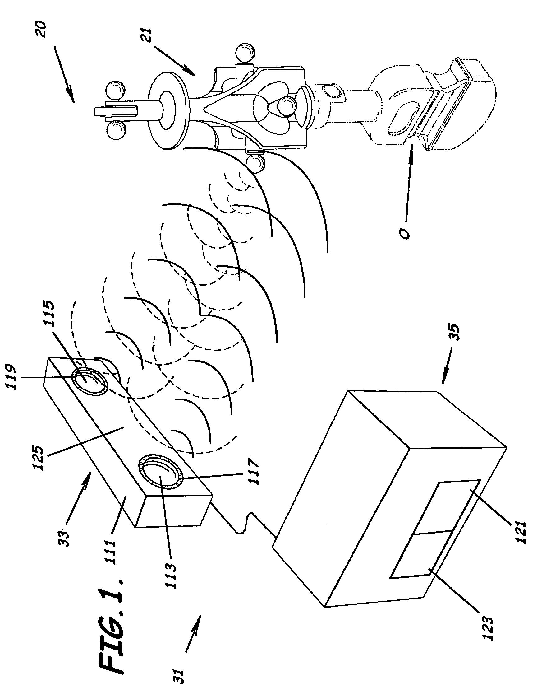
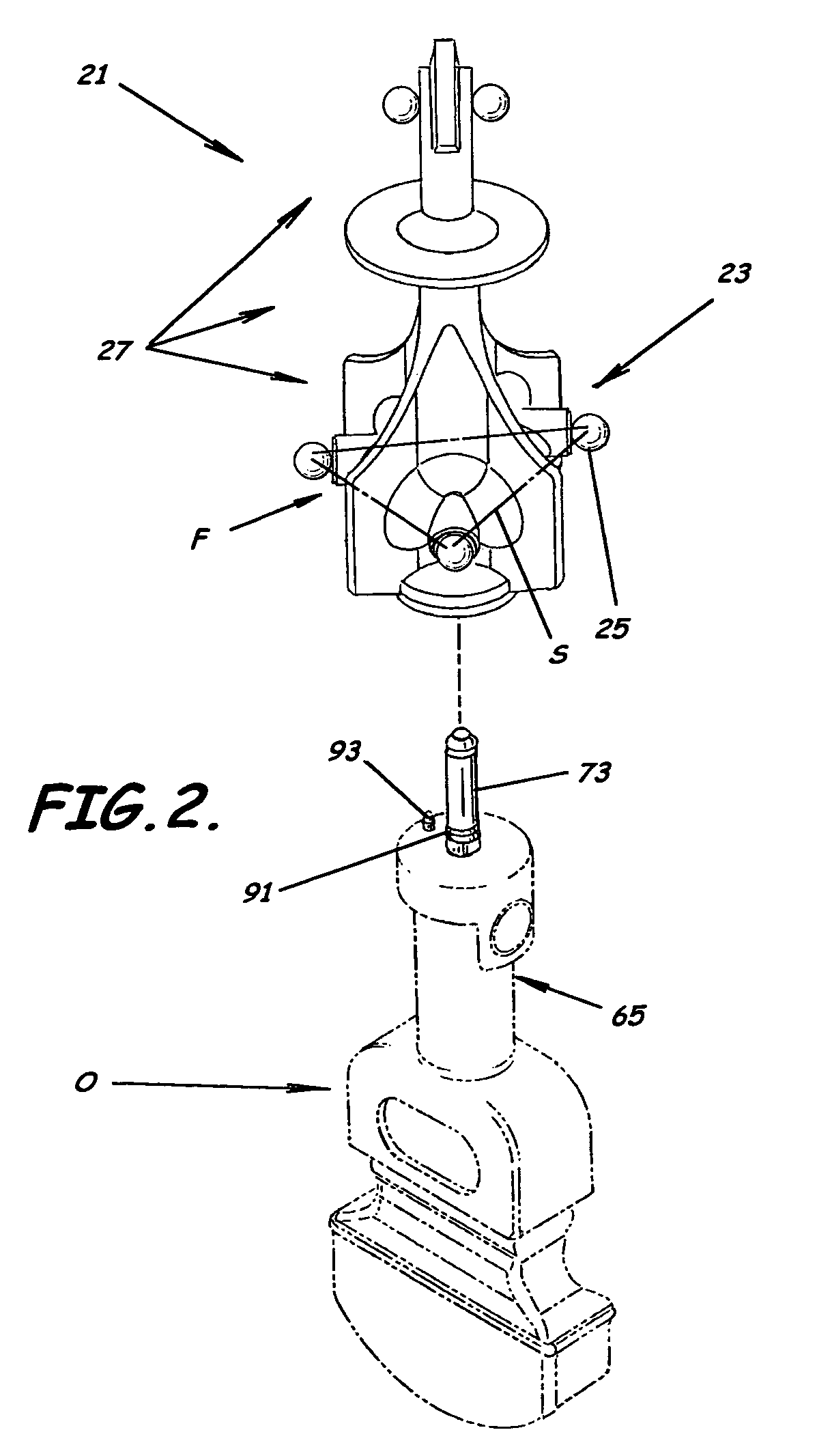
[0046]As illustrated in FIGS. 1-14, embodiments of the present invention advantageously provide a system 20, tracker 21, and methods for tracking a three-dimensional position and an orientation of a movable object O. As perhaps b...


PUM


Abstract

A system to track a three-dimensional position and an orientation of a movable object and associated methods are provided. The system includes a tracker having an optically trackable body adapted to connect to the movable object. A plurality of optical indicators are connected or mounted to the optically trackable body to form a plurality of geometric figures. A plurality of obfuscating flanges optically separate the optical indicators from each other to prevent each of the optical indicators from becoming optically coincident with another optical indicator when viewed along a preselected viewing path. The system also includes an apparatus to track the tracker having an optical detector to simultaneously detect the three-dimensional position of at least three of the plurality of optical indicators and a determiner to determine the three-dimensional position and orientation of the optically trackable body from the position of the optical indicators.

Description

BACKGROUND OF THE INVENTION[0001]1. Field of the Invention[0002]The present invention relates to tracking apparatus. More specifically, the present invention relates to a system, a tracker, and related methods for tracking spatial position and orientation of an object.[0003]2. Description of the Related Art[0004]It is often desired to track the position and orientation of an object. For example, in the electronics industry it is often necessary to match surfaces or insert parts in predetermined positions. This is especially significant where a robot or robotic arm is used. In the medical field, it is often necessary to track the position of a medical instrument in order to determine the location of an object within a body. For example, knowledge of the position of a surgical tool during neurosurgery or location of a target such as a tumor while radiation therapy treatment is occurring, have always been critical issues.[0005]Also, in the medical field, recent diagnostic advances such...

Claims


Application Information

Patent Timeline
Patent Type & Authority Patents(United States)
IPC IPC(8): G01B11/26
CPCA61B5/06A61B8/4245A61B19/5244A61B19/54A61B2017/0046G01S17/875A61B2019/5255A61B2019/5276A61B2019/5437A61B2019/5483A61B2017/00477A61B5/064A61B34/20A61B90/39A61B2034/2055A61B2090/378A61B2090/3937A61B2090/3983
Inventor SMETAK, EDWARD CHARLESSCHERCH, JOHN DAVID
Owner BEST MEDICAL INT
Why Eureka
Try Eureka