Image recording apparatus and image correction method

a recording apparatus and image technology, applied in the field of image recording apparatus and image correction method, can solve the problems of marked decline in image quality, abnormal recording, fault in recorded image, etc., and achieve the effect of enhancing the effect of preventing image abnormalities

Inactive Publication Date: 2007-10-30
FUJIFILM CORP
View PDF23 Cites 25 Cited by
  • Summary
  • Abstract
  • Description
  • Claims
  • Application Information

AI Technical Summary

Benefits of technology

[0015]The present invention has been contrived in view of the foregoing circumstances, an object thereof being to process an image recording apparatus and an image correction method whereby desirable image recording is achieved by preventing image faults, such as artifacts occurring due to abnormalities in recording elements, in accordance with the image recorded.
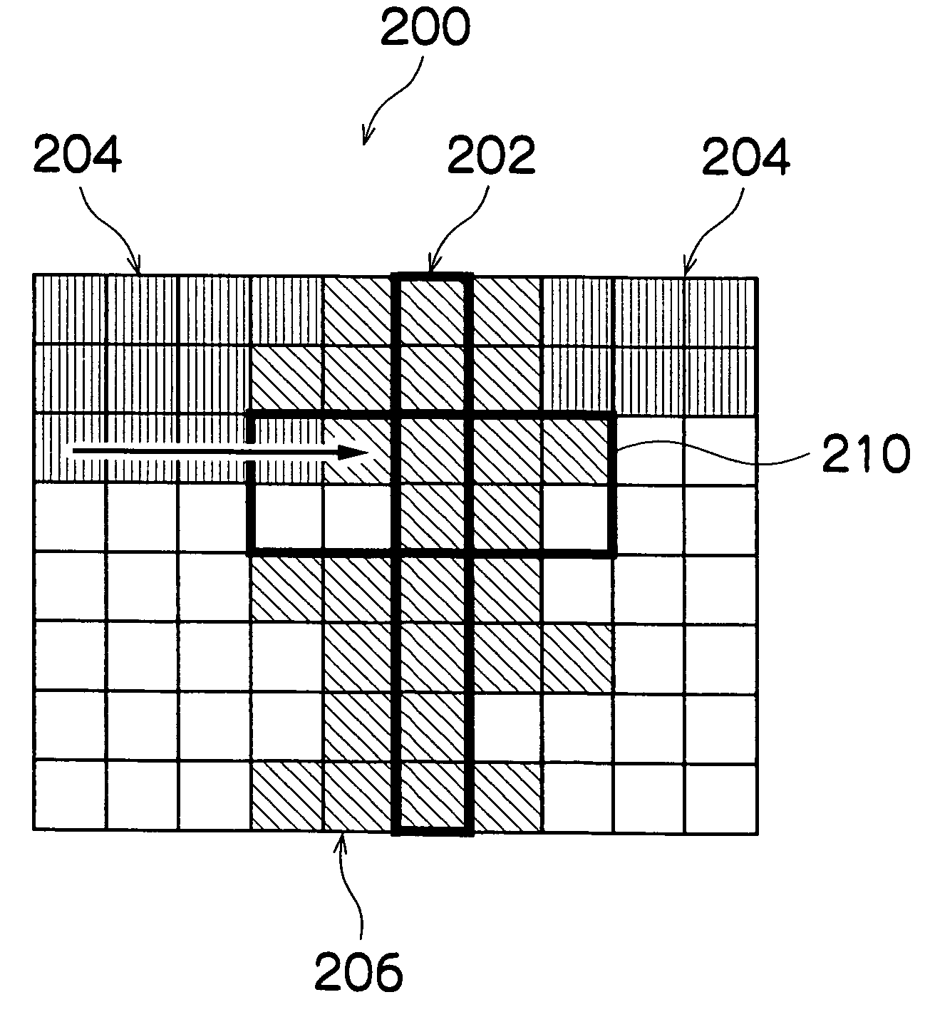
[0017]When an abnormal recording element is specified from among the recording elements of the recording head, a correction dot pattern is set on the basis of the information relating to the abnormal recording element, and quantization processing is carried out using this correction dot pattern, thereby generating dot data in such a manner that image recording is performed by recording elements other than the abnormal recording element. Consequently, it is possible to obtain a desirable image in which artifacts, such as banding caused by an abnormality in a recording element, are prevented.
[0018]The correction dot pattern is a dot pattern which is fixed in order to prevent an artifact, such as banding, and it has a width of at least two pixels. Dots are arranged (in other words, dots are set to an “on” state) at pixel positions adjacent to the pixel positions corresponding to the abnormal recording elements, in such a manner that the artifact is prevented.
[0030]It is possible to increase the effect of reducing image abnormalities by using the fixed correction dot pattern to perform quantization processing for the pixels corresponding to the abnormal recording element and the pixels peripheral to the pixels corresponding to the abnormal recording element. On the other hand, it is possible to make the boundary between the region where the correction dot pattern is used and the region where it is not used less conspicuous, by reducing the ratio of the contribution of the correction dot pattern, in the pixels which are more distant from the abnormal recording element.
[0047]According to the present invention, when an abnormality recording element is identified from among the recording elements of a recording head, half-tone processing is carried out on the basis of a fixed correction dot pattern. Furthermore, since the image is divided selectively into a region where half-toning is performed using the correction dot pattern and a region where quantization processing is performed so as to maintain the average value, by using a correction control pattern which controls the region where the correction dot pattern is used and the region where the correction dot pattern is not used it is possible perform a desirable quantization process in accordance with the image to be formed. Hence, the effect of preventing image abnormalities can be enhanced.

Problems solved by technology

If an abnormality, such as a fault or decline in performance, occurs in a recording element provided in a recording head, then a dot abnormality occurs.
Namely, a dot is omitted or the desired dot is not formed in the position where the dot was originally to have been formed on the recording medium, and therefore, a fault occurs in the recorded image.
When performing one-pass recording of recording elements using a full line recording head comprising a row of recording elements of a length corresponding to the entire printable width of the recording medium, image defects (artifacts), such a stripe-shaped omissions or non-uniformities in density, are formed extending in the relative conveyance direction of the recording head and the recording medium, thus leading to a marked decline in image quality.
However, when correcting an image by using the recording elements peripheral to an abnormal recording element, there is a risk that artifacts, such as dot omissions or non-uniformities in density, may actually become more conspicuous depending on the image processing method (dot forming method) used.
Furthermore, in the method for reduction of artifacts in reproduced images described in Japanese Patent Application Publication No. 2002-234216 and the image processing apparatus described in Japanese Patent Application Publication No. 09-083796, there is no disclosure with regard to the image correction technology used when a recording element is not functioning correctly, for instance, when it is suffering an ejection failure.

Method used


Image

  • Image recording apparatus and image correction method
  • Image recording apparatus and image correction method
  • Image recording apparatus and image correction method

Examples


Embodiment Construction

General Composition of Inkjet Recording Apparatus

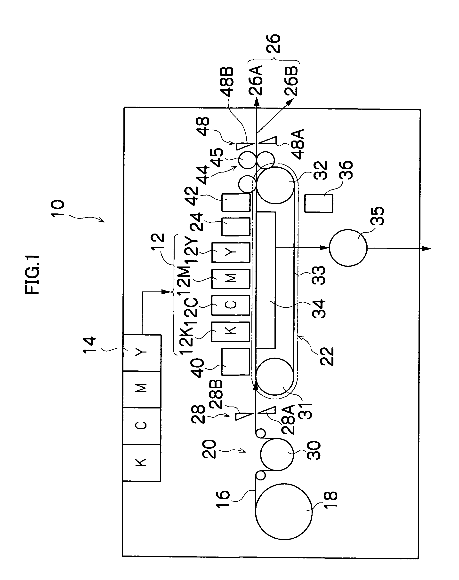
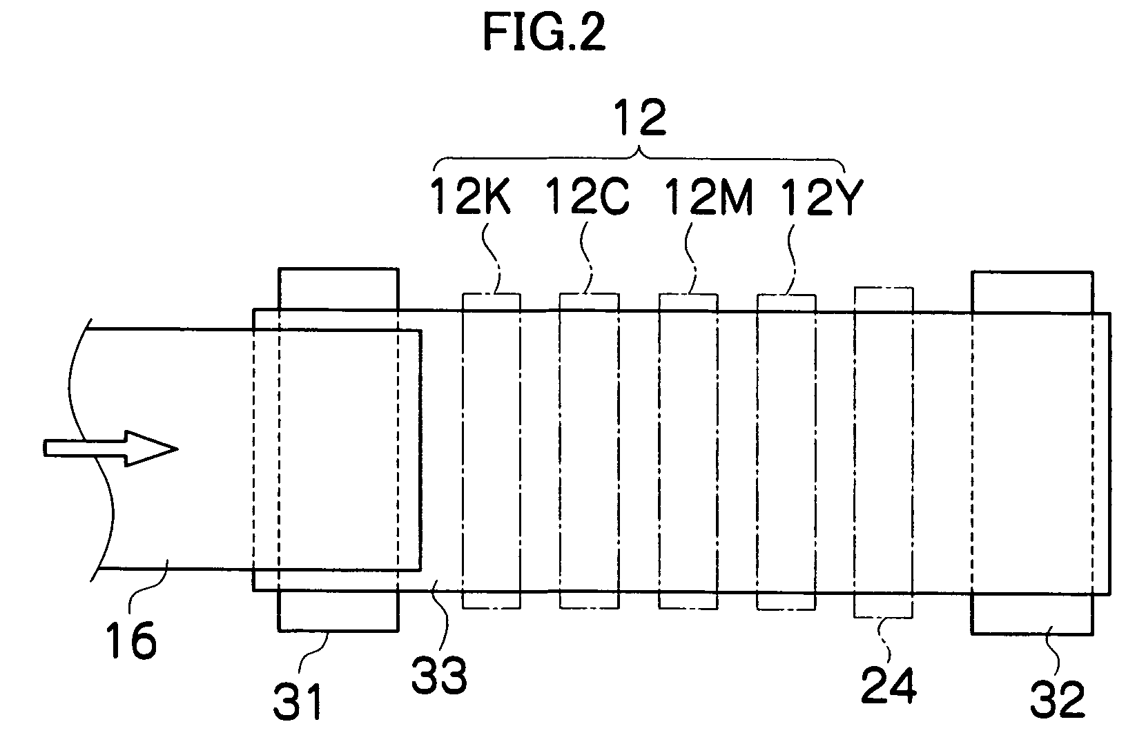
[0064]FIG. 1 is a diagram of the general composition of an inkjet recording apparatus including a print head (recording head) according to an embodiment of the present invention. As shown in FIG. 1, the inkjet recording apparatus 10 comprises: a printing unit 12 having a plurality of inkjet heads 12K, 12C, 12M and 12Y provided for ink colors of black (K), cyan (C), magenta (M) and yellow (Y), respectively; an ink storing and loading unit 14 for storing inks of K, C, M and Y to be supplied to the print heads 12K, 12C, 12M and 12Y; a paper supply unit 18 for supplying recording paper 16; a decurling unit 20 removing curl in the recording paper 16; a suction belt conveyance unit 22 disposed facing the nozzle face (ink-droplet ejection face) of the print unit 12, for conveying the recording paper 16 while keeping the recording paper 16 flat; a print determination unit 24 for reading the printed result produced by the printing unit 12; and...


PUM


Abstract

The image recording apparatus comprises: a recording head including recording elements which record an image onto a recording medium; an abnormal recording element specification device which specifies an abnormal recording element from the recording elements of the recording head; a correction dot pattern setting device which sets a correction dot pattern for preventing an image abnormality due to the abnormal recording element; an image processing device which generates dot data by performing quantization processing on image data using the correction dot pattern set by the correction dot pattern setting device; and a drive device which drives the recording elements according to the dot data generated by the image processing device.

Description

BACKGROUND OF THE INVENTION[0001]1. Field of the Invention[0002]The present invention relates to an image recording apparatus and an image correction method, and more particularly, to image correction technology for preventing faults in an image caused by abnormalities in recording elements.[0003]2. Description of the Related Art[0004]In recent years, inkjet recording apparatuses have come to be used widely as data output apparatuses for outputting images, documents, or the like. The inkjet recording apparatus drives recording elements, such as nozzles provided in a recording head, in accordance with data so as to form data onto a recording medium, such as recording paper, by means of ink ejected from the nozzles.[0005]In the inkjet recording apparatus, a desired image is formed on a recording medium by causing a recording head having a plurality of nozzles and a recording medium to move relatively to each other while causing ink droplets to be ejected from the nozzles.[0006]If an a...

Claims


Application Information

Patent Timeline
Patent Type & Authority Patents(United States)
IPC IPC(8): G06F15/00
CPCB41J2/04508B41J29/393B41J2/04586B41J2/0451
Inventor YAMAZAKI, YOSHIROU
Owner FUJIFILM CORP
Why Eureka
Try Eureka