Method and apparatus for performing directional re-scan of an adaptive antenna

a technology of adaptive antennas and antennas, applied in the field of methods and antenna apparatus, can solve problems such as multipath fading, radio frequency signal transmitted from a sender (either a base station or mobile subscriber unit) may encounter interference, fade or dropout of the received signal,

Inactive Publication Date: 2007-10-30
IPR LICENSING INC
View PDF9 Cites 14 Cited by
  • Summary
  • Abstract
  • Description
  • Claims
  • Application Information

AI Technical Summary

Benefits of technology

[0014]The intercell interference problem is exacerbated in CDMA systems, since the subscriber units in adjacent cells may typically be transmitting on the same frequency. For example, generally, two subscriber units in adjacent cells operating at the same carrier frequency but transmitting to different base stations will interfere with each other if both signals are received at one of the base stations. One signal appears as noise relative to the other. The degree of interference and the receiver's ability to detect and demodulate the intended signal is also influenced by the power level at which the subscriber units are operating. If one of the subscriber units is situated at the edge of a cell, it transmits at a higher power level, relative to other units within its cell and the adjacent cell, to reach the intended base station. But, its signal is also received by the unintended base station, i.e., the base station in the adjacent cell. Depending on the relative power level of two same-carrier frequency signals received at the unintended base station, it may not be able to properly identify a signal transmitted from within its cell from the signal transmitted from the adjacent cell. What is needed is a way to reduce the subscriber unit antenna's apparent field of view, which can have a marked effect on the operation of the forward link (base to subscriber) by reducing the apparent number of interfering transmissions received at a base station. A similar improvement is needed for the reverse link, so that the transmitted signal power needed to achieve a particular receive signal quality can be reduced.BRIEF DESCRIPTION OF THE PRESENT INVENTION
[0016]The invention provides an apparatus and method for efficiently configuring the antenna apparatus to maximize the effective radiated and / or received energy. The antenna apparatus includes multiple antenna elements and a like number of adjustable weight control components. As is well known in the art, the weight control components are controllable to adjust the phase, amplitude, phase and amplitude and / or delay of the signal coupled to each of the antenna elements. The weight control components (e.g., phase shifter, delay line, amplifier with variable gain) are jointly and independently operable to affect the direction of reverse link signals transmitted from the subscriber unit on each of the antenna elements and the receiving direction for forward link signals transmitted to the subscriber unit.
[0017]Further, the present invention provides an apparatus and method for initiating antenna angle re-scans during which the antenna is sequentially pointed in a plurality directions away from the primary direction so that the antenna directivity can be dynamically adjusted to compensate for changing radio frequency environments. It is advantageous to execute the re-scan process as pedestrian movement or other changes in the physical environment at the subscriber unit can modify the direction from which the best signal is received by the subscriber unit as transmitted by the base station (or vice versa). The antenna is therefore controlled to change its steered direction to achieve the optimum signal performance between the subscriber unit and the base station,
[0018]It is further advantageous, according to the teachings of the present invention, to identify certain advantageous times for executing the re-scan process to minimize interruptions to the data transmission and minimize the loss of data packets, thereby maintaining optimum system performance.
[0020]Through the use of an array of antenna elements and execution of the re-scan process, the antenna apparatus increases the effective transmit power per bit transmitted. Thus, the number of active subscriber units in a cell may remain the same while the antenna apparatus of this invention allows for an increase in data rates for each subscriber unit beyond those achievable by prior art antennas. Alternatively, if data rates are maintained at a given rate, more subscriber units may become active in a cell using the antenna apparatus described herein. In either case, the cell capacity increases, as measured by the sum total of data being communicated at any time.
[0021]In accordance with the teachings of the present invention, forward link communications capacity can be increased as well, due to the directional reception capabilities of the antenna as optimized during the re-scan process. Since a properly directed antenna is less susceptible to interference from adjacent cells, the forward link cell capacity can be increased by adding more users or by increasing cell radius.

Problems solved by technology

Various problems are inherent in prior art antennas used on mobile subscriber units in wireless communications systems.
One such problem is called multipath fading.
In multipath fading, a radio frequency signal transmitted from a sender (either a base station or mobile subscriber unit) may encounter interference on route to the intended receiver.
As a result, the original and reflected signals may partially cancel each other (destructive interference), resulting in fading or dropouts in the received signal; hence the term multipath fading.
Single element antennas are highly susceptible to multipath fading.
A single element antenna has no way of determining the direction from which a transmitted signal is sent and cannot be tuned or attenuated to more accurately detect and receive a signal arriving from any particular direction.
The dual element antenna described in the aforementioned reference is also susceptible to multipath fading due to the symmetrical and opposing nature of the hemispherical lobes formed by the antenna pattern when the phase shifter is activated.
That is, if the original signal reflects from an object beyond or behind the intended receiver (with respect to the sender) and reflects back to the intended receiver from the opposite direction as the directly received signal, a phase difference in the two signals can create destructive interference due to multipath fading.
Another problem present in cellular communication systems is inter-cell interference.
Intercell interference occurs when a mobile subscriber unit near the edge of one cell transmits a signal that crosses over that edge into a neighboring cell and interferes with communications taking place within the neighboring cell.
Typically, intercell interference occurs when the same or similar frequencies are used for communications in neighboring cells.
The problem of intercell interference is compounded by the fact that subscriber units near the edges of a cell typically use higher transmit powers so that the signals they transmit can be effectively received by the intended base station located at the cell center.
Consider that the signal from another mobile subscriber unit located beyond or behind the intended receiver may arrive at the base station at the same power level, representing additional interference.
The intercell interference problem is exacerbated in CDMA systems, since the subscriber units in adjacent cells may typically be transmitting on the same frequency.
For example, generally, two subscriber units in adjacent cells operating at the same carrier frequency but transmitting to different base stations will interfere with each other if both signals are received at one of the base stations.
Depending on the relative power level of two same-carrier frequency signals received at the unintended base station, it may not be able to properly identify a signal transmitted from within its cell from the signal transmitted from the adjacent cell.

Method used


Image

  • Method and apparatus for performing directional re-scan of an adaptive antenna
  • Method and apparatus for performing directional re-scan of an adaptive antenna
  • Method and apparatus for performing directional re-scan of an adaptive antenna

Examples


Embodiment Construction

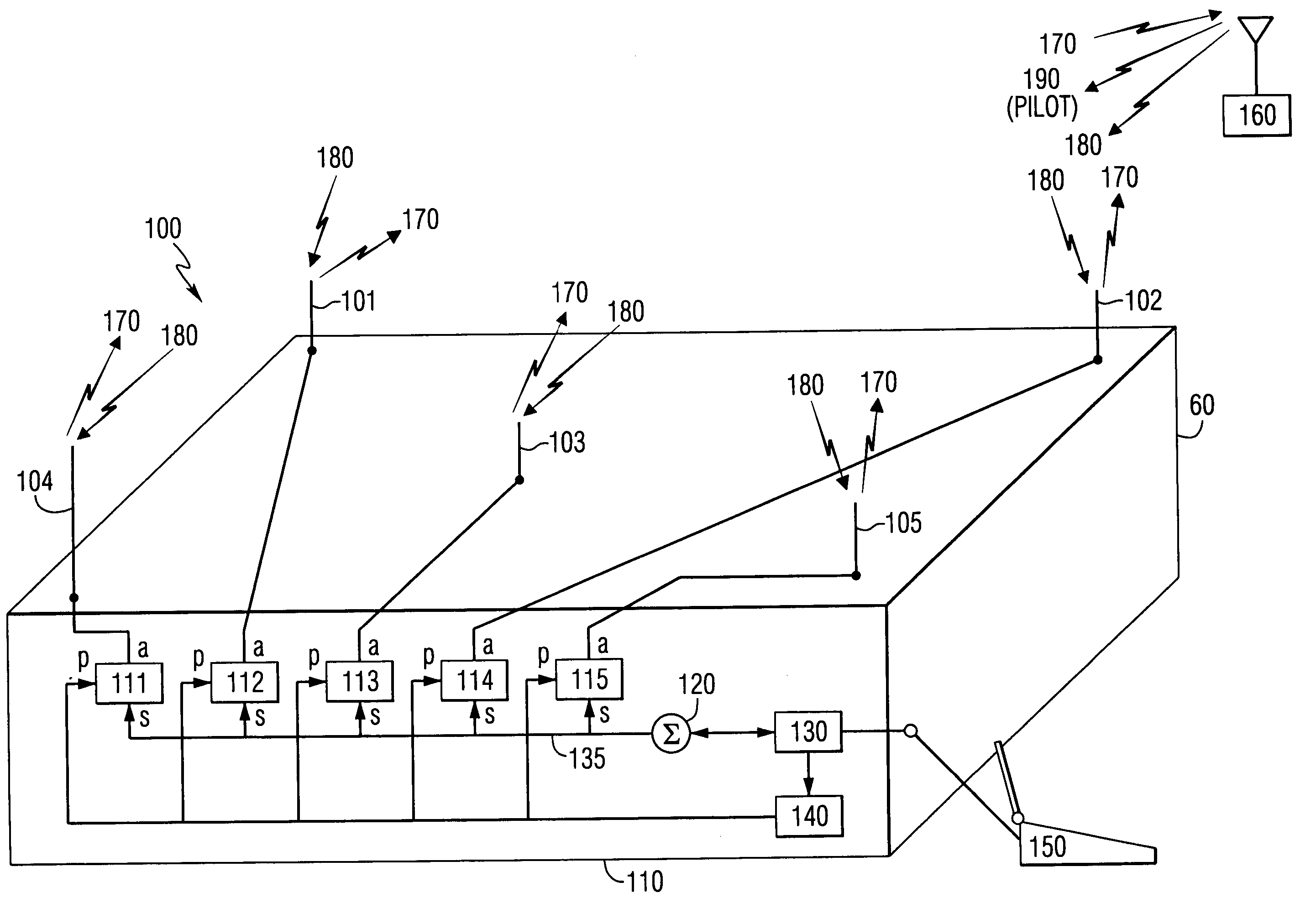
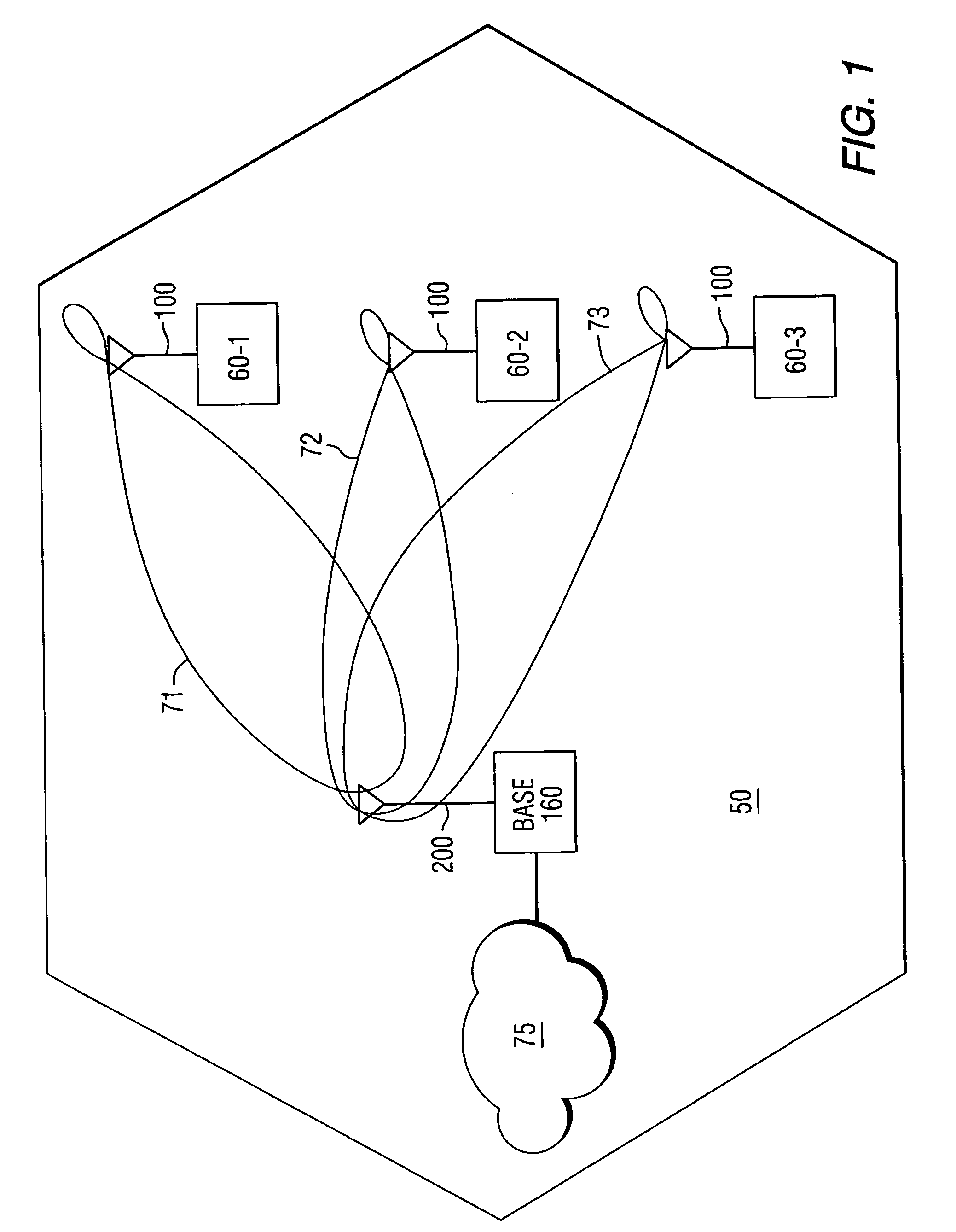
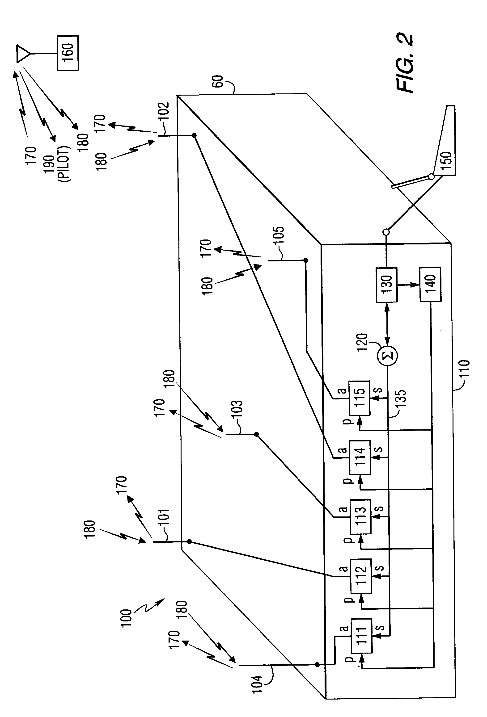
[0029]FIG. 1 illustrates one cell 50 of a typical CDMA cellular communication system. The cell 50 represents a geographical area in which mobile subscriber units 60-1 through 60-3 communicate with a centrally located base station 160. Each subscriber unit 60 is equipped with an antenna 100 configured according to the present invention. The subscriber units 60 are provided with wireless data and / or voice services by the system operator and can connect devices such as, for example, a laptop computer, a portable computer, a personal digital assistant (PDA) or the like through base station 160 to a network 75, which can be the public switched telephone network (PSTN), a packet switched computer network, such as the Internet, a public data network or a private network or intranet. The base station 160 communicates with the network 75 over any number of different available communications protocols such as primary rate ISDN, or other LAPD based protocols such as IS-634 or V5.2, or even TCP...


PUM


Abstract

An antenna for use with a receiver in a wireless communications system includes antenna elements for generating antenna patterns, and a first module for applying weights to a signal received at each of the antenna elements to generate a selected one of the antenna patterns. A second module detects the received signal at each of the antenna elements. A combiner combines the received signal detected at each of the antenna elements to produce a combined received signal for a selected antenna pattern. A third module determines a signal quality metric for the combined received signal at each selected antenna pattern. The first module is responsive to the determined signal quality metrics for adjusting the weights to generate a preferred antenna pattern.

Description

CROSS-REFERENCE TO RELATED APPLICATIONS[0001]This application is a Continuation of U.S. patent application Ser. No. 09 / 776,396 filed Feb. 2, 2001 now U.S. Pat. No. 6,792,290, which is a Continuation-In-Part of U.S. patent application Ser. No. 09 / 579,084 filed May 25, 2000 now U.S. Pat. No. 6,304,215, which is a divisional application of U.S. patent application Ser. No. 09 / 210,117 filed Dec. 11, 1998 now U.S. Pat. No. 6,100,843, which is a continuation application of U.S. patent application Ser. No. 09 / 157,736 filed Sep. 21, 1998 now abandoned the entire teachings of which are incorporated herein by reference.FIELD OF THE INVENTION[0002]This invention relates to mobile (or portable) cellular communication systems, and more particularly to an antenna apparatus for use by mobile subscriber units to provide beam forming transmission and reception capabilities.BACKGROUND OF THE INVENTION[0003]Code division multiple access (CDMA) communication systems provide wireless communications betwe...

Claims


Application Information

Patent Timeline
Patent Type & Authority Patents(United States)
IPC IPC(8): H04M1/00H01Q1/24H01Q3/26H04B7/08
CPCH01Q1/246H01Q3/2605H04B7/0874
Inventor PROCTOR, JR., JAMES ARTHURLA MONT, JR., LAWRENCE WAYNENELSON, JR., GEORGE RODNEYGAINEY, KENNETH MARVIN
Owner IPR LICENSING INC
Why Eureka
Try Eureka