
Arrangement in connection with feedback control system

Inactive Publication Date: 2007-11-06
GE HEALTHCARE FINLAND
View PDF38 Cites 48 Cited by
  • Summary
  • Abstract
  • Description
  • Claims
  • Application Information

AI Technical Summary

Benefits of technology

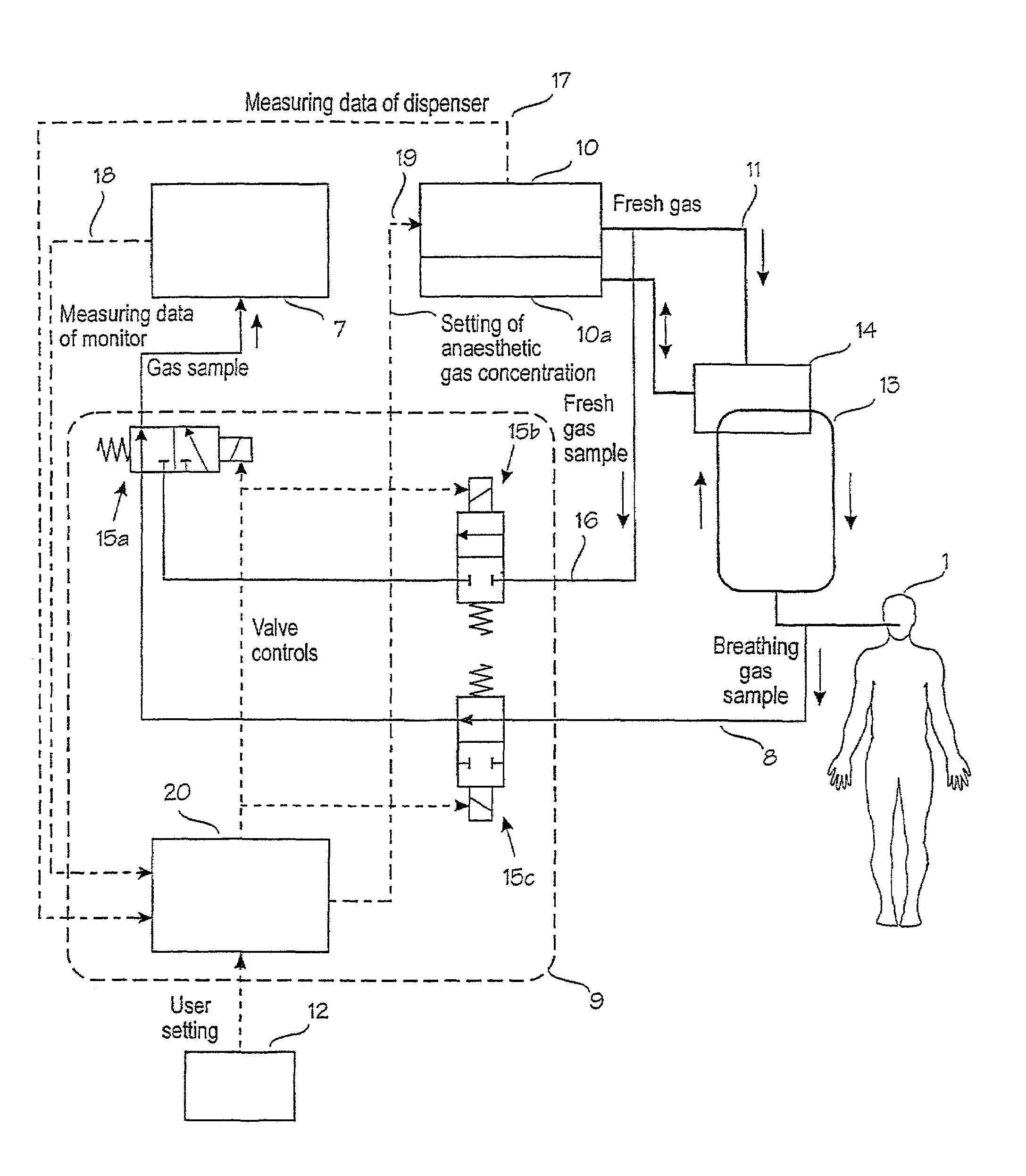
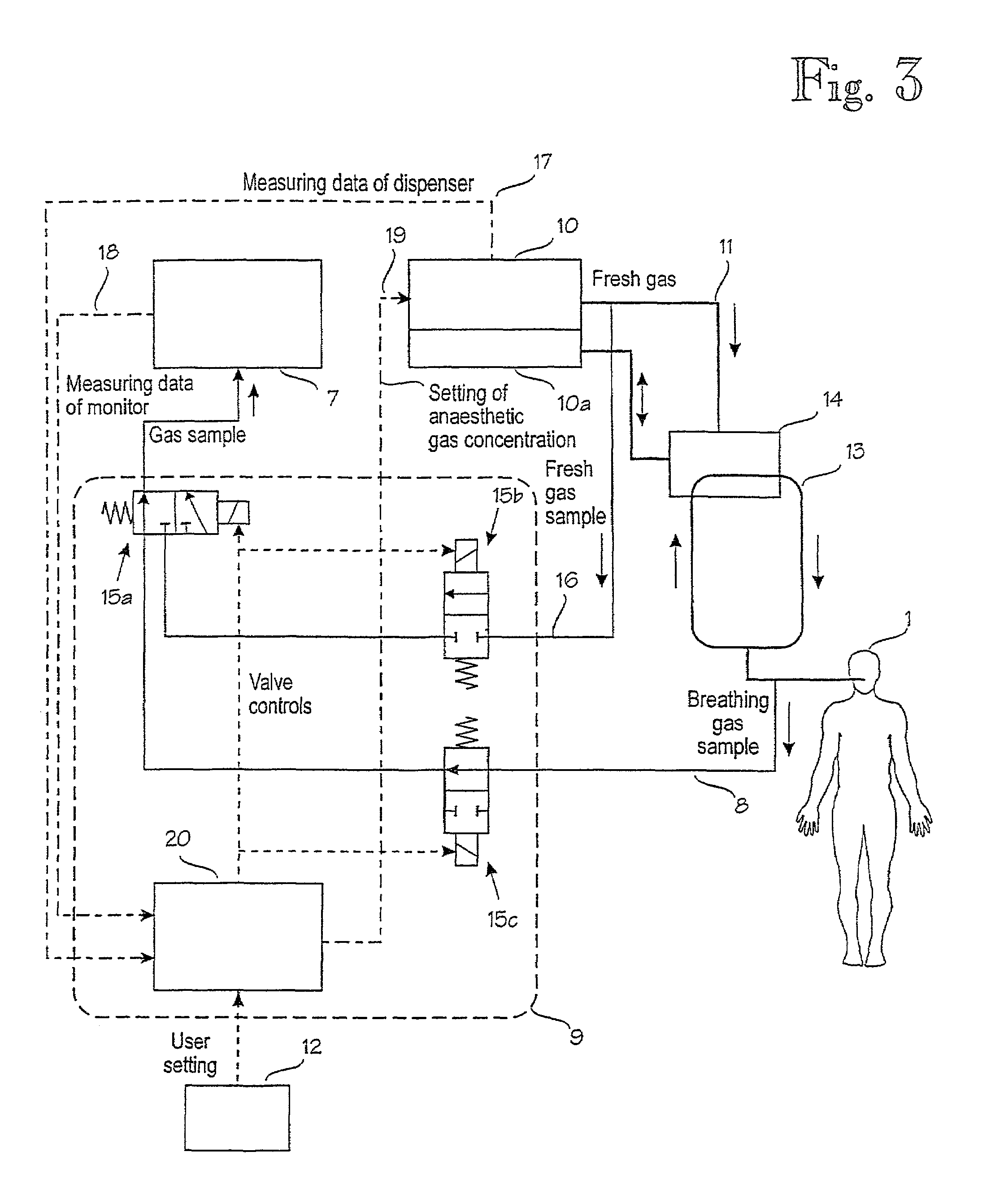
[0012]The object of the invention is to provide an arrangement by which the prior art disadvantages can be eliminated. This is achieved by the arrangement according to the invention, characterized in that the arrangement comprises means adapted to feed a reference signal to the measuring device periodically and that the controlling device is adapted to compare the measuring value obtained on the basis of the reference signal with the real reference value of the reference signal and adapted to take a safety measure when the measuring value and the reference value differ substantially from each other.
[0013]Above all the invention provides the advantage that measuring devices on the market do not have to be redesigned for one-fault situations. A fault is recognised by an external controller which automatically checks the operation of the measuring device as a whole by means of reference measurement. The automatic checking can usually be performed by employing a very simple technique. An independent reference source is also easily available in the system. Due to simplicity, the actual controller can be straightforwardly planned against one-fault situations, and the end result is advantageous in all respects.

Problems solved by technology

Due to indirectness and a long time constant, the exact adjustment of measuring values is slow and difficult, which leads to variation in patient values, and this in turn may have harmful effects on the end result of nursing.
An automatic feedback complicates the system considerably and brings new possibilities of fault situations, the existence of which should be taken into account when implementing the equipment.
As stated above, a safety risk is substantially present in the feedback control system, as only devices for patient care are planned to cope with one-fault situations in operational environments.

Method used


Image

  • Arrangement in connection with feedback control system
  • Arrangement in connection with feedback control system
  • Arrangement in connection with feedback control system

Examples


Embodiment Construction

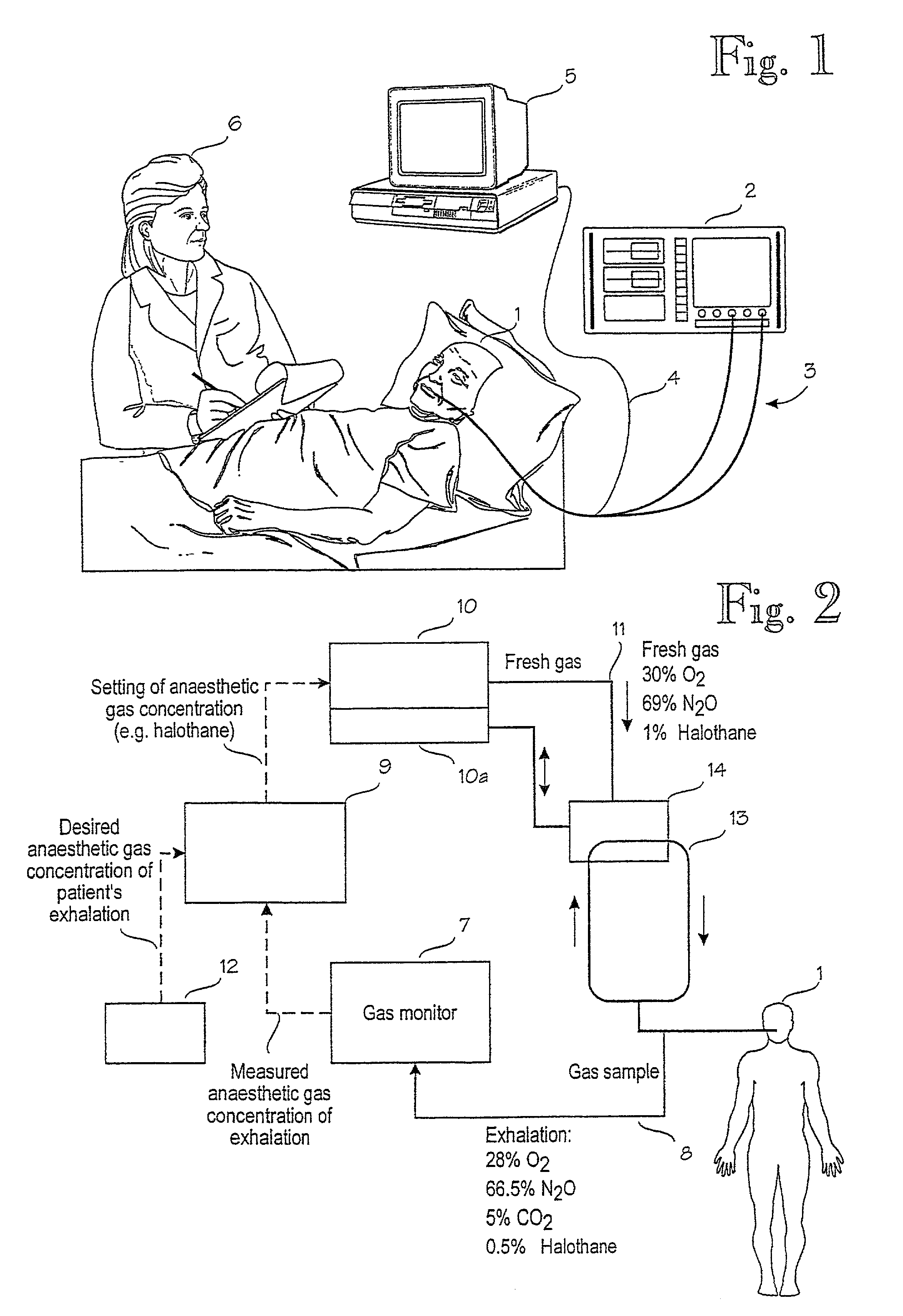
[0018]FIG. 1 shows a schematic view of an operational environment of equipment used in patient care. A patient 1 is connected to a device used in patient care, which, in the example of FIG. 1, is a combination of a gas mixer and ventilator 2. The patient is connected by means of a patient circuit 3. From the patient circuit 3 there is a measuring connection 4 to a monitor 5 which monitors the condition of the patient. A healthcare person 6 supervises the condition of the patient on the basis of the measuring information on the condition of the patient provided by the monitor 5 and, when necessary, adjusts set values of the device used in patient care such that the measuring information corresponds to the desired value of the moment, as explained above.

[0019]FIG. 2 for its part shows a control system, in which a gas dispenser of an anaesthesia machine is automatically controlled on the basis of a signal given by breathing gas measurement of the monitor. If, as a result of a fault sit...


PUM


Abstract

The invention relates to an arrangement in connection with a feedback control system, the arrangement comprising a controllable device (10), a measuring device (7), a controlling device (9) and a user interface by which the controlling device (9) can be monitored by means of set values. The measuring device (7) is adapted to measure a measuring value (8) from a measuring point, which measuring value is dependent on the operation of the controllable device and the controlling device (9) is adapted to monitor the controllable device (10) on the basis of the measuring value and set values. To improve safety, the arrangement comprises means (15a, 15b, 15c) adapted to feed a reference signal (16) to the measuring device (7) periodically. The controlling device (9) is adapted to compare a measuring value (18) obtained from the reference signal with the real reference value (17) of the reference signal and adapted to take a safety measure when the measuring value (18) and the real reference value (17) differ substantially from each other.

Description

CROSS REFERENCE TO RELATED APPLICATION[0001]The present application is the U.S. national stage application of International Application PCT / FI99 / 01007, filed Dec. 3, 1999, which international application was published on Jun. 15, 2000 as International Publication WO 00 / 33904 in the English language. The International Application claims the priority of Finnish Patent Application 982653, filed Dec. 8, 1998.SUMMARY OF THE INVENTION[0002]The invention relates to an arrangement in connection with a feedback control system, the arrangement comprising a controllable device, a measuring device, a controlling device and a user interface by which the controlling device can be monitored by means of set values, whereby the measuring device is adapted to measure a measuring value from a measuring point, which measuring value is dependent on the operation of the controllable device, and the controlling device is adapted to monitor the controllable device on the basis of the measuring values and s...

Claims


Application Information

Patent Timeline
IPC IPC(8): A61M16/00A61B9/00A62B27/00G08B3/00G08B5/00A61M16/10G05B9/02G05B23/02
CPCA61M16/104G05B23/0235G05B9/02A61M2205/18A61M2205/33A61M2230/43A61M2230/40A61M2230/437
Inventor SARELA, ANTTILONCAR, MARIO
Owner GE HEALTHCARE FINLAND
Learn More