Memory card

a memory card and memory chip technology, applied in the field of memory cards, can solve the problems of affecting the reliability of connection, so as to increase the number of laminated semiconductor chips. the effect of reliability

Inactive Publication Date: 2007-11-06
RENESAS ELECTRONICS CORP
View PDF24 Cites 44 Cited by
  • Summary
  • Abstract
  • Description
  • Claims
  • Application Information

AI Technical Summary

Benefits of technology

[0018]The effects obtained by the typical inventions among the inventions disclosed in this application will briefly be explained hereinafter.
[0019]The invention can realize a memory card having a mechanism capable of surely preventing a wrong insertion into a memory card slot.
[0020]The invention can realize a memory card that can keep connection reliability with a connector terminal in the memory card slot for a long period of time.
[0021]The invention can realize a memory card having a card structure capable of increasing the number of laminated semiconductor chips.

Problems solved by technology

When the memory card of this type is inserted into a memory card of a cellular phone, users may make a mistake in the direction of the card (the direction of front or rear or the direction of front or back), so that they may frequently insert the memory card in the wrong direction.
When the card is inserted in the wrong direction, the connector terminal in the slot is bent or the external connection terminal of the card and the connector terminal not corresponding to this external connection terminal erroneously come in contact with each other, thereby entailing a disadvantage of deteriorating or damaging the circuit in the semiconductor chip.
In particular, miniaturizing the card makes it difficult to tell which direction is front or rear or which is front or back.

Method used


Image

  • Memory card
  • Memory card
  • Memory card

Examples


embodiment 1

[0059]A memory card according to this embodiment is an ultra-small, large-capacity multi-function memory card having a security function in addition to a memory function. It is used as inserted into a memory card slot such as, for example, a third-generation cellular phone.

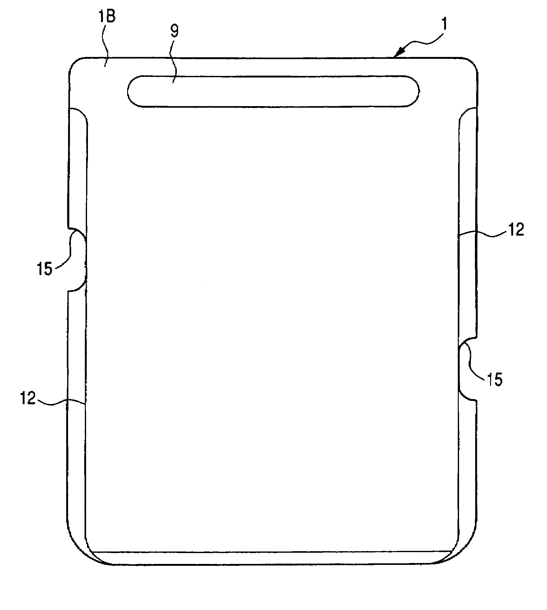
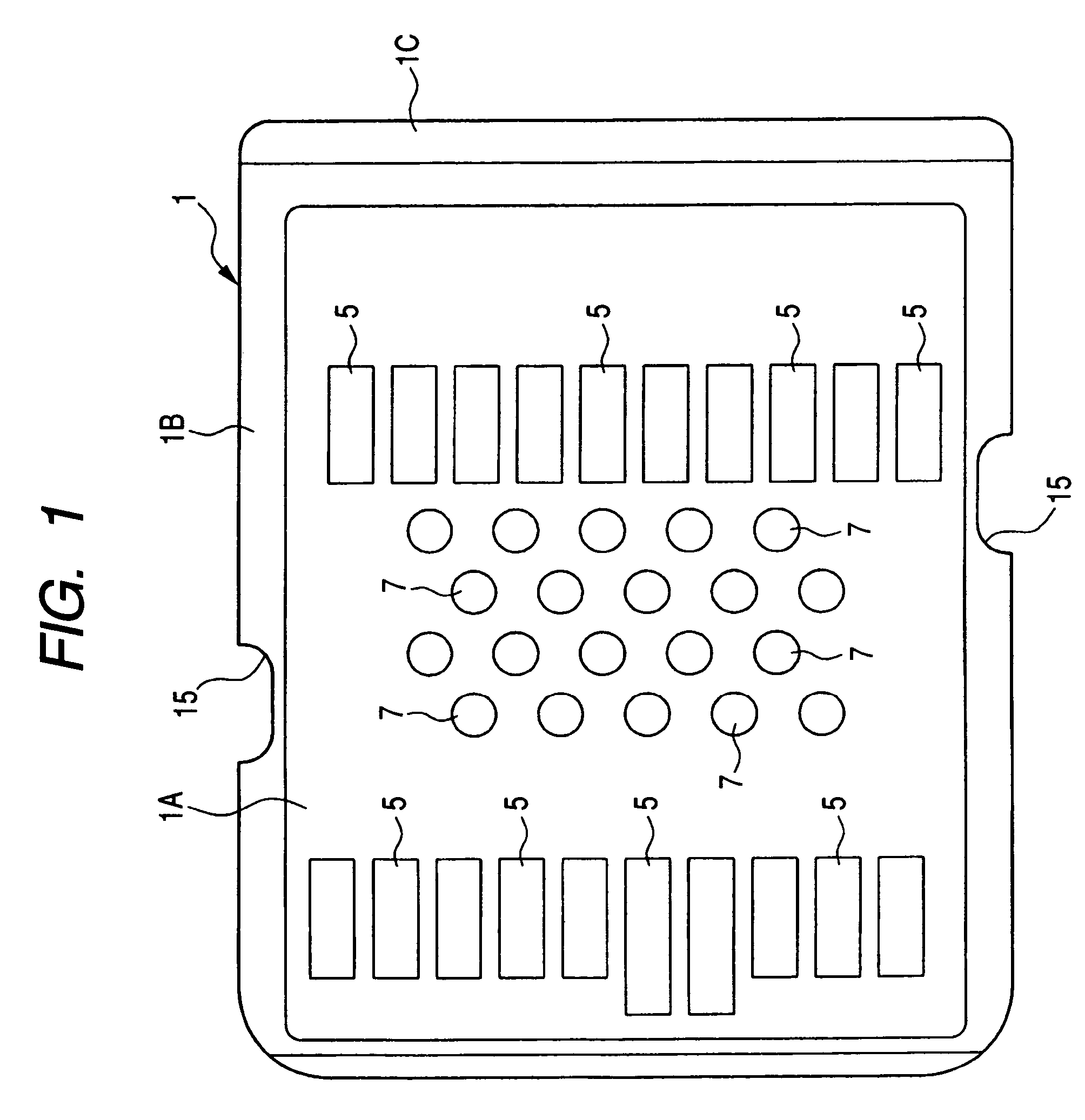
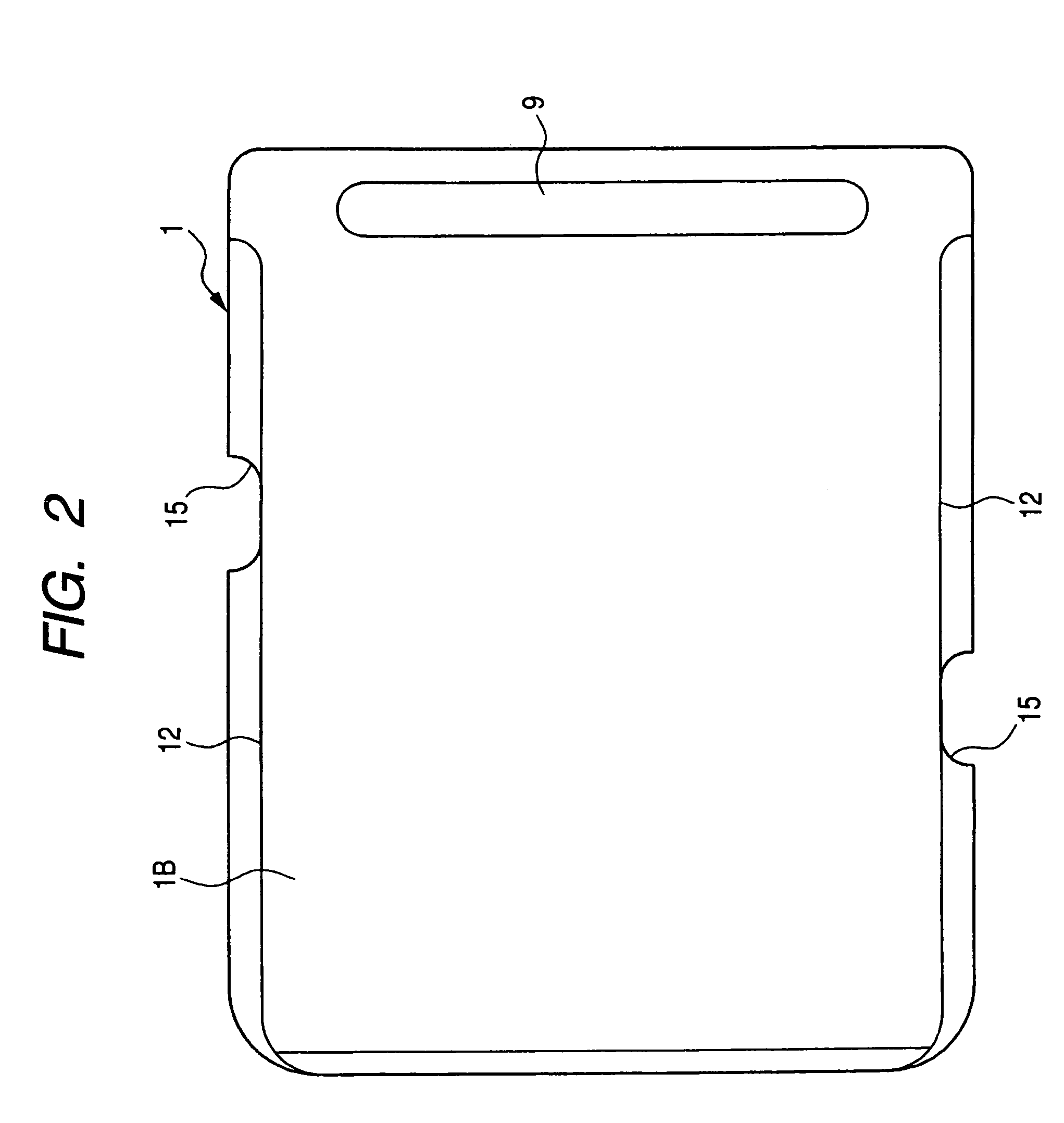
[0060]FIGS. 1 and 2 are plan views showing an outer appearance of the multi-function memory card according to this embodiment, in which FIG. 1 shows a face on which external connection terminals are formed and FIG. 2 shows its opposite face. Further, FIG. 3 is a sectional view showing an essential part of this memory card. It should be noted that the face on which the external connection terminals are formed is referred to as a back face, while the face shown in FIG. 2 is referred to as a front face.

[0061]The multi-function memory card 1 according to this embodiment is composed of a card body 1A and a cap (casing) 1B for housing the card body. The card body 1A is composed of a wiring substrate 2 made of glass epox...

embodiment 2

[0103]FIGS. 19 and 20 are plan views showing the outer appearance of the multi-function memory card according to this embodiment, in which FIG. 19 shows a face (back face) where the external connection terminals are formed and FIG. 20 shows its opposite face (front face).

[0104]In the multi-function memory card 1 according to this embodiment, the notch channels 15 formed at both side faces of the cap 1B are arranged in the vicinity of the external connection terminals 5 at the back row. Specifically, two notch channels 15 are positioned so as to be shifted toward the trailing edge of the cap 1B compared to the embodiment 1 and further, they are arranged so as to be equally spaced from the trailing edge of the cap 1B.

[0105]As described above, the notch channel 15 is provided for preventing the erroneous contact with the terminals 11 that are non-corresponding to the external connection terminals 5 when the multi-function memory card 1 is inserted into or removed from the slot of the c...

embodiment 3

[0116]FIG. 31 is a plan view of the multi-function memory card according to this embodiment wherein the arrangement of the external connection terminals 5 are changed in order to provide interchangeability to a memory card of different type having different standard, and FIGS. 32 and 33 are plan views of an adaptor to which this multi-function memory card is inserted, in which FIG. 32 shows a front face side and FIG. 33 shows a back face side (the face on which the external connection terminals are formed).

[0117]The adaptor 30 shown in FIG. 32 and FIG. 33 has an outer dimension and external connection terminals 31 same as those of a memory card (hereinafter simply referred to as memory stick) called “Memory Stick Duo” manufactured by Sony Corporation in order to provide interchangeability with this memory stick. The memory stick has ten external connection terminals, so that the adaptor 30 also has ten external connection terminals 31 (#1 to #10). In the multi-function memory card 1...


PUM


Abstract

This invention is to provide an ultra-miniaturized, thin-sized memory card provided with a mechanism for preventing a wrong insertion to a memory card slot. A multi-function memory card is composed of a card body and a cap for housing the card body. The card body is made of mold resin that encapsulates plural semiconductor chips mounted on a main surface of a wiring substrate. The card body is housed into the cap with the back face of the wiring substrate facing outward. Guide channels are provided at both side faces of the cap for preventing that the card is inserted upside down. Further, a convex section is provided at the trailing edge of the cap for preventing that the card is inserted in the wrong direction.

Description

[0001]The present application claims priority from Japanese patent application No. 2004-257244 filed on Sep. 3, 2004 and No. 2004-129602 filed on Apr. 26, 2004 the content of which is hereby incorporated by reference into this application.BACKGROUND OF THE INVENTION[0002]The present invention relates to a memory card, and more particularly to a technique that is effectively applied to an ultra-small, thin-sized memory card used as inserted into a card slot of a communication portable terminal device such as a cellular phone.[0003]A cellular phone has functions of Internet connection, mail transmission, image capture, navigation or the like, in addition to a function of a telephone. Recently, a security function is also added, example of which includes a non-contact IC card.[0004]With the multi-functionalization of a cellular phone as described above, various cards in which multi-functionalization has been promoted with a miniaturization and reduction in size have also been developed...

Claims


Application Information

Patent Timeline
Patent Type & Authority Patents(United States)
IPC IPC(8): H01L23/02G06K21/00H01R13/73H05K1/18B42D15/10G06K7/00G06K13/06G06K17/00G06K19/07G06K19/077
CPCG06K7/0021G06K13/06G06K19/077G06K19/07732G06K19/07741H01L2224/73265H01L2224/32225H01L2224/32145Y10S439/948H01L2924/01019H01L2924/19041H01L2924/01079H01L2225/06562H01L2924/01057H01L2924/01078H01L2224/48227H01L2924/00012H01L24/73A45B25/08A45B2200/1081
Inventor NISHIZAWA, HIROTAKAOSAWA, KENJIOSAKO, JUNICHIROWADA, TAMAKISUGIYAMA, MICHIAKITOTSUKA, TAKASHI
Owner RENESAS ELECTRONICS CORP
Why Eureka
Try Eureka