Computing blending functions for the tiling of overlapped video projectors

a video projector and video blending technology, applied in the field of computer graphics, can solve problems such as difficulty in achieving

Active Publication Date: 2007-11-06
ORACLE INT CORP
View PDF16 Cites 83 Cited by
  • Summary
  • Abstract
  • Description
  • Claims
  • Application Information

AI Technical Summary

Benefits of technology

[0013]A system for correcting the intensities of pixels supplied to a projector. An image generated by the projector has a number of regions formed by the overlapping of the image with one or more other images generated by one or more other projectors. The system includes: a first unit configured to generate a horizontal scaling value; a second unit configured to generate a vertical scaling value; a first multiplier configured to multiply the horizontal scaling value and the vertical scaling value to obtain a scaling coefficient, and a set of one or more additional multipliers configured to multiply components of an input pixel by the scaling coefficient to determine components for an output pixel. The first unit and second unit compute their respective scaling values in a way that allows for regions whose boundaries non-aligned in the vertical direction.

Problems solved by technology

This is quite difficult to achieve, because of unavoidable differences in the brightness, color temperature, and other characteristics of the projectors, and because of the human visual system's sensitivity to visual artifacts having high spatial frequency, such as abrupt boundaries.

Method used


Image

  • Computing blending functions for the tiling of overlapped video projectors
  • Computing blending functions for the tiling of overlapped video projectors
  • Computing blending functions for the tiling of overlapped video projectors

Examples


Embodiment Construction

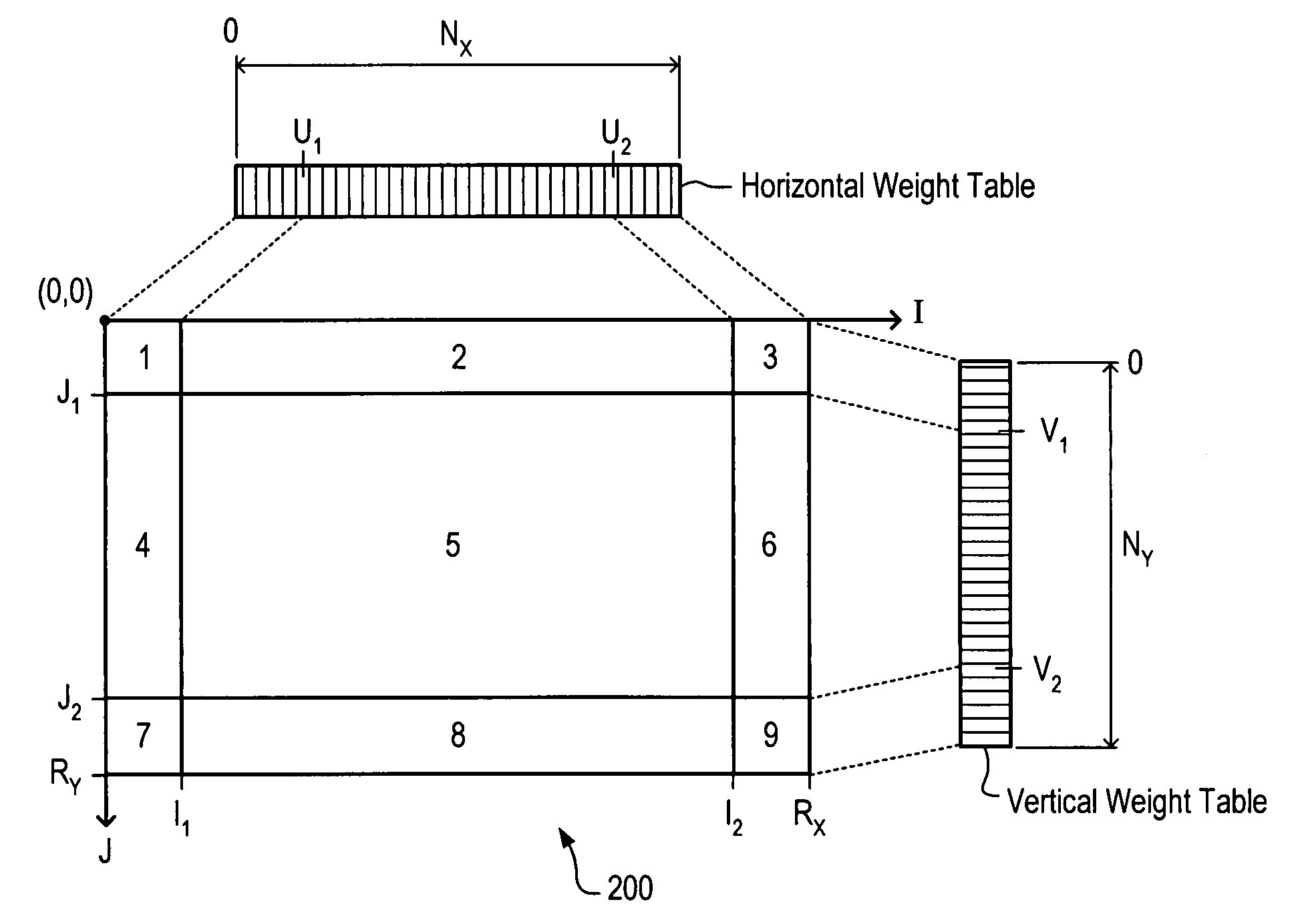
[0032]In one set of embodiments, a compensation unit may be configured to receive a video stream and scale the RGB values of pixels in the video stream. The video stream conforms to a video raster having horizontal resolution RX and vertical resolution RY. The scaled pixels form an output video stream which is used to drive a projector. The projector generates a time-varying image on a display surface in response to the output stream (or an analog video signal derived from the output stream). Under somewhat idealized conditions, the generated image may resemble image 200 as suggested in FIG. 6.

[0033]Regions 1-9 are indicated within image 200. Regions 1-4 and 6-9 are regions of overlap with neighboring images generated by other projectors. (For example, visualize four other projectors that generate four neighboring images: one above, one below, one to the right, and one to the left of image 200.) Region 5 is that portion of image 200 which is not shared with any other projector. Obse...


PUM


Abstract

A system for correcting the intensities of pixels supplied to a projector. An image generated by the projector has a number of regions formed by the overlapping of the image with one or more other images generated by one or more other projectors. The system includes: a first unit configured to generate a horizontal scaling value; a second unit configured to generate a vertical scaling value; a first multiplier configured to multiply the horizontal scaling value and the vertical scaling value to obtain a scaling coefficient, and a set of one or more additional multipliers configured to multiply components of an input pixel by the scaling coefficient to determine components for an output pixel. The first unit and second unit compute their respective scaling values in a way that allows for regions whose boundaries non-aligned in the vertical direction.

Description

BACKGROUND OF THE INVENTION[0001]1. Field of the Invention[0002]This invention relates generally to the field of computer graphics and, more particularly, to a graphics system configured to compute blending functions for overlapped video projectors.[0003]2. Description of the Related Art[0004]For large format visualization applications, especially for group presentation, or for immersive virtual reality display, it is often desirable to use several video projectors whose projected images tile a display surface. The surface may be curved or otherwise non-flat.[0005]A major requirement for many of these visualization applications is that there be no seam or visual discontinuity between the regions displayed by the respective projectors. This is quite difficult to achieve, because of unavoidable differences in the brightness, color temperature, and other characteristics of the projectors, and because of the human visual system's sensitivity to visual artifacts having high spatial frequ...

Claims


Application Information

Patent Timeline
Patent Type & Authority Patents(United States)
IPC IPC(8): G09G5/00
CPCG09G3/001H04N9/3197H04N9/3182H04N9/3188H04N9/3147G09G2320/0233G09G2340/10
Inventor NAEGLE, NATHANIEL DAVIDCASTLE, CLAYTON W.
Owner ORACLE INT CORP
Why Eureka
Try Eureka