Image blurring correction apparatus

a correction apparatus and image technology, applied in the field of image blurring correction apparatus, can solve the problems of difficult control of time and position, discomfort in camera operation and image, and difficulty in preventing image disorganization

Active Publication Date: 2007-11-06
FUJI PHOTO OPTICAL CO LTD
View PDF9 Cites 55 Cited by
  • Summary
  • Abstract
  • Description
  • Claims
  • Application Information

AI Technical Summary

Benefits of technology

[0012]Preferably, the image blurring correction stopping device changes the speed at which the shooting range of the image taking optical system is returned to the reference position so that the speed in a case where the focal length of the image taking optical system is short is lower than the speed in a case where the focal length is long.
[0014]According to the present invention, in the case where it is determined that the camera is performing pan or tilt operation and the shooting range displaced by the image blurring correction device is returned to the reference position, the speed thereof is changed according to the focal length, and may be reduced if set on the wide-side in particular. Therefore, it prevents the problem that the sense of discomfort arises due to the swingback on the pan or tilt operation.
[0017]According to the present invention, in the case where it is determined that the camera is performing pan or tilt operation and the shooting range displaced by the image blurring correction is returned to the reference position, the shooting range is kept at the fixed position until the predetermined time elapses, and so the shooting range is not abruptly displaced in a reverse direction so that disorder of the images is prevented.

Problems solved by technology

If the image blurring correction is performed on the pan or tilt operation, however, it is not desirable because the image blurring occurs after finishing the pan or tilt operation so that sense of discomfort may arise in the camera operation and image.
Even in the case where an image blurring correction is stopped on pan or tilt operation as described above, however, there is a problem that a phenomenon (swingback) occurs, in which an image jitters (jerks) due to operation of returning a vibration-proof lens to a position of a displacement amount 0 (reference position) as if the speed of the pan or tilt operation is instantaneously changed.
In the case where the zoom is set on a wide-side, however, there is a problem that the swingback conspicuously appears even when performing the pan or tilt operation at the same speed as when setting it on the tele-side and the sense of discomfort arises in the camera operation and image.
In the case where a filter constant in a filter such as an IIR filter is changed to return the vibration-proof lens to the reference position on the pan or tilt operation, there is a problem that, as the operation depends on the nature of the filter, it is so difficult to control the time and position that the vibration-proof lens cannot be returned to the reference position by intended control.

Method used


Image

  • Image blurring correction apparatus
  • Image blurring correction apparatus
  • Image blurring correction apparatus

Examples


Embodiment Construction

[0033]Hereafter, preferred embodiments of an image blurring correction apparatus according to the present invention will be described in detail by referring to the attached drawings.

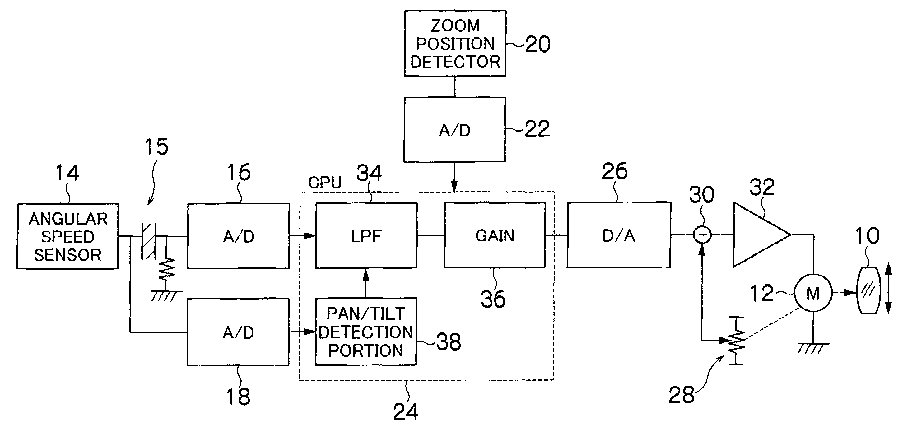
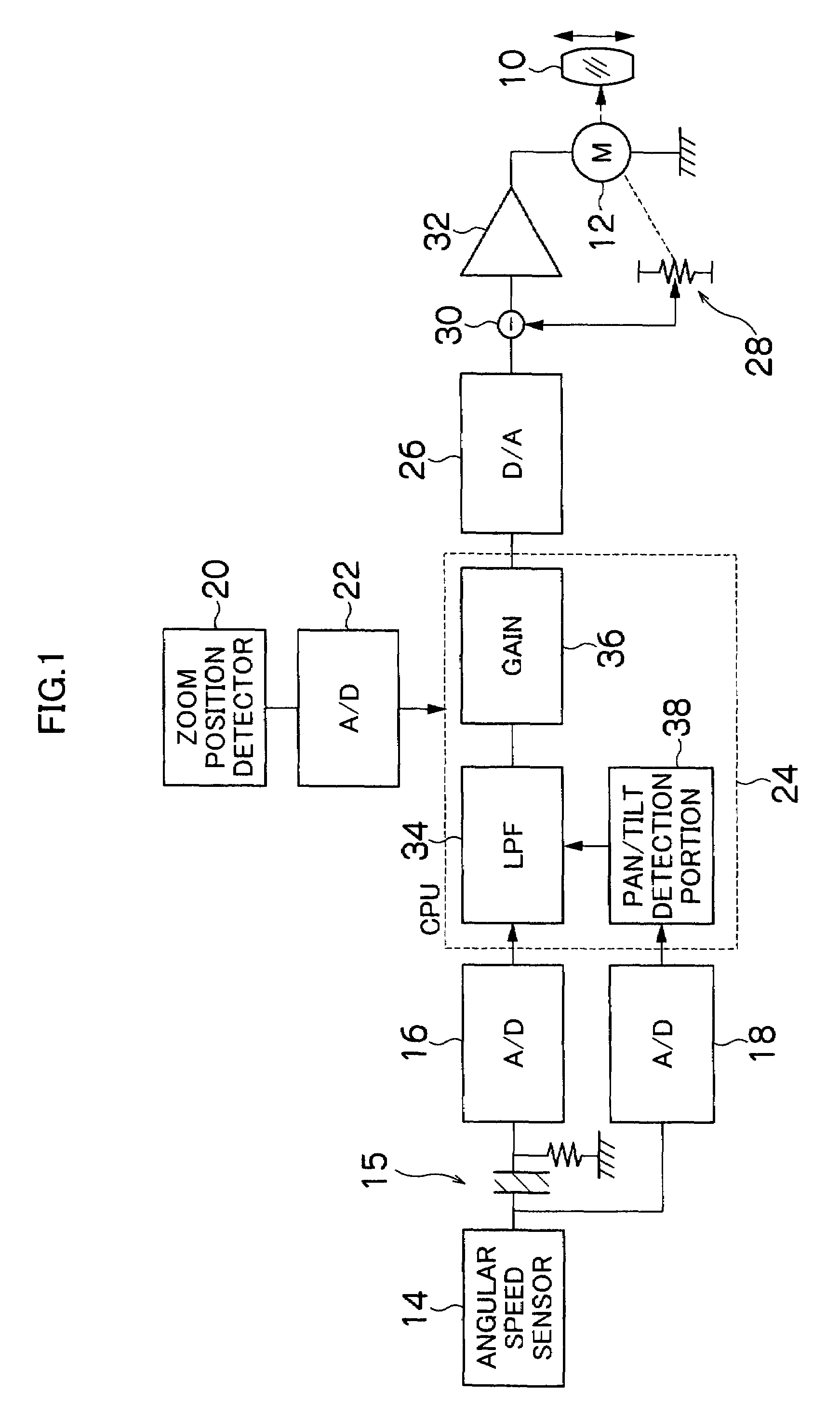
[0034]FIG. 1 is a block diagram showing the embodiment of the image blurring correction apparatus according to the present invention. The image blurring correction apparatus is mounted on a lens apparatus (taking lens) for a TV camera, a movie camera or a still camera and so on for instance. A vibration-proof lens 10 shown in FIG. 1 is placed to be movable up and down (vertical direction) and right and left (horizontal direction) within a surface perpendicular to an optical axis in the lens apparatus or an image taking optical system of the camera on which this apparatus is mounted. The vibration-proof lens 10 is driven vertically or horizontally by a motor 12, and if the camera (image taking optical system) is vibrated, it is moved by the motor 12 to a position for preventing an image blurring (position...


PUM


Abstract

When the camera is performing the pan or tilt operation on performing image blurring correction, the image blurring correction is stopped and a vibration-proof lens is returned to a reference position at a speed that is changed according to a focal length of the zoom lens and is reduced if the zoom lens is set on a wide-side in particular so as to prevent a sense of discomfort due to swingback on the pan or tilt operation. The vibration-proof lens may be kept at a fixed position for a fixed time and returned to the reference position after the fixed time elapses so as to alleviate disorder of an image. The control subject for correcting the image blurring may be returned to the reference position by a predetermined function of which variable is time so as to exert control after stopping the image blurring correction on the pan or tilt operation suitably as intended.

Description

BACKGROUND OF THE INVENTION[0001]1. Field of the Invention[0002]The present invention relates to an image blurring correction apparatus, and in particular, to the image blurring correction apparatus for correcting (preventing) an image blurring of a camera due to vibration.[0003]2. Description of the Related Art[0004]For instance, as for an image blurring correction apparatus of a TV camera, there is a known one wherein a vibration-proof lens is placed to be movable within a surface perpendicular to an optical axis in an image taking optical system, and if the camera (image taking optical system thereof) is vibrated, the vibration-proof lens is driven by an actuator in a direction for counteracting the vibration so as to correct an image blurring. As for such an image blurring correction apparatus, the vibration applied to the camera is detected by a blurring detection sensor (angular speed sensor, acceleration sensor, etc.) so that a displacement amount of the vibration-proof lens ...

Claims


Application Information

Patent Timeline
Patent Type & Authority Patents(United States)
IPC IPC(8): H04N5/228G03B17/00H04N5/262G06T5/00H04N5/232
CPCG03B5/00H04N5/23248H04N5/23258H04N5/23287G06T5/003H04N5/23267G03B2217/005G03B2205/0015G06T2207/20201H04N23/683H04N23/68H04N23/6812H04N23/687
Inventor HIGURASHI, AIKOHISHINUMA, KENJI
Owner FUJI PHOTO OPTICAL CO LTD
Why Eureka
Try Eureka