
Hand tool for chopping ice

Inactive Publication Date: 2007-11-13
AMES TRUE TEMPER
View PDF17 Cites 30 Cited by
  • Summary
  • Abstract
  • Description
  • Claims
  • Application Information

AI Technical Summary

Benefits of technology

[0009]In use, the user will grasp the outer tubular handle proximate its upper end and using his / her arms will plunge the chopper tool in a vertical motion, or at an angle to the surface of the ice, with the first chopper blade impacting the ice layer, followed immediately by a pulse as the second blade secured to distal end of the rod impacts on the first blade impulsing the first blade on the ice. It is believed that the combination of blows in rapid succession produce harmonics in the pressure waves traveling through the ice that aids in the disintegration of the ice.

Problems solved by technology

During winter in colder climes, a problem arises when snow melts and then refreezes on driveways and sidewalks.
Ice patches can be hazardous and are the cause of many slip and fall accidents.
Depending upon the thickness of the ice layer and how intimately it is engaged with the underlying concrete or asphalt, it may take many, many blows of the chopper blade to crack and chip away the buildup of ice.

Method used


Image

  • Hand tool for chopping ice
  • Hand tool for chopping ice
  • Hand tool for chopping ice

Examples


Embodiment Construction

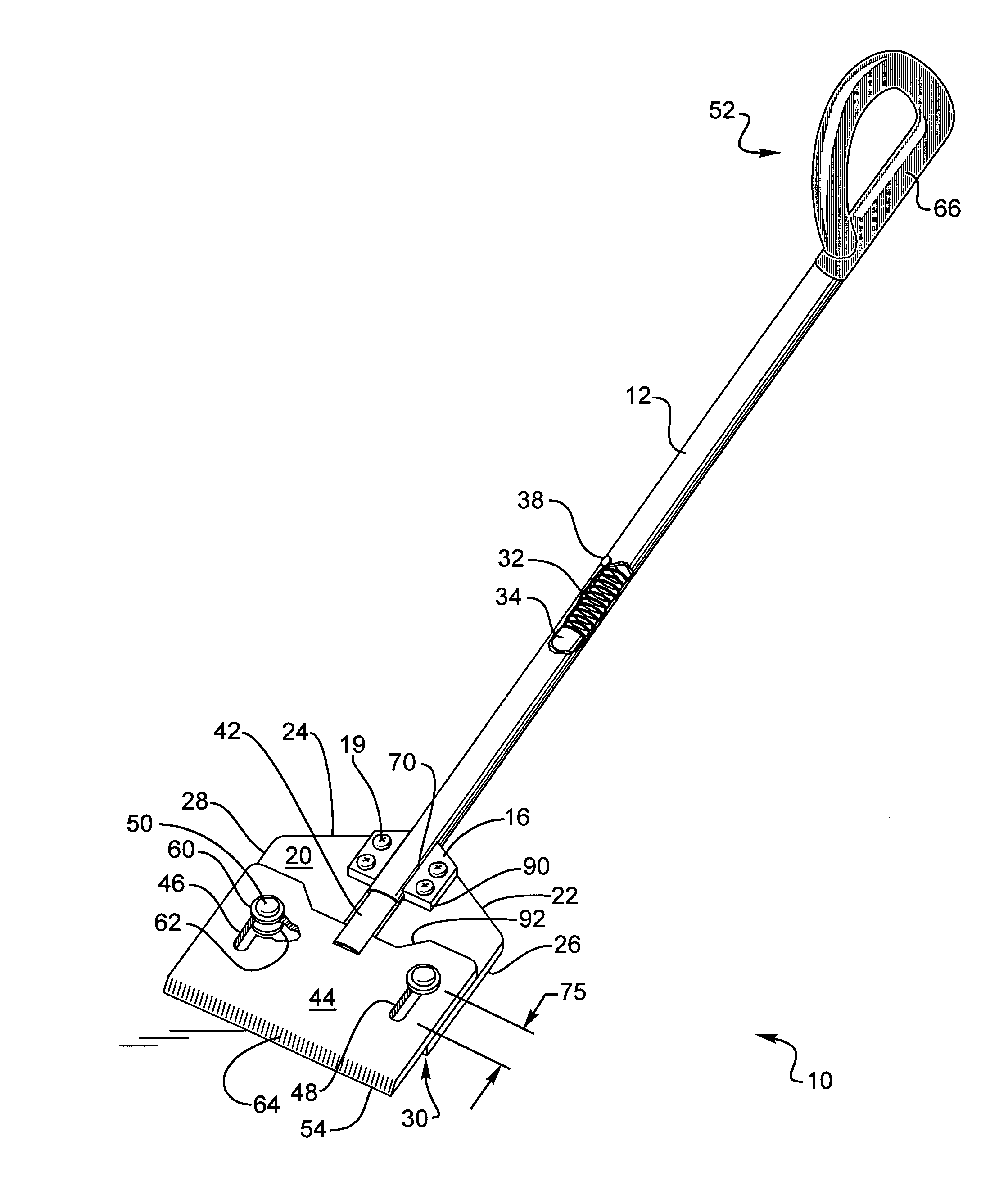
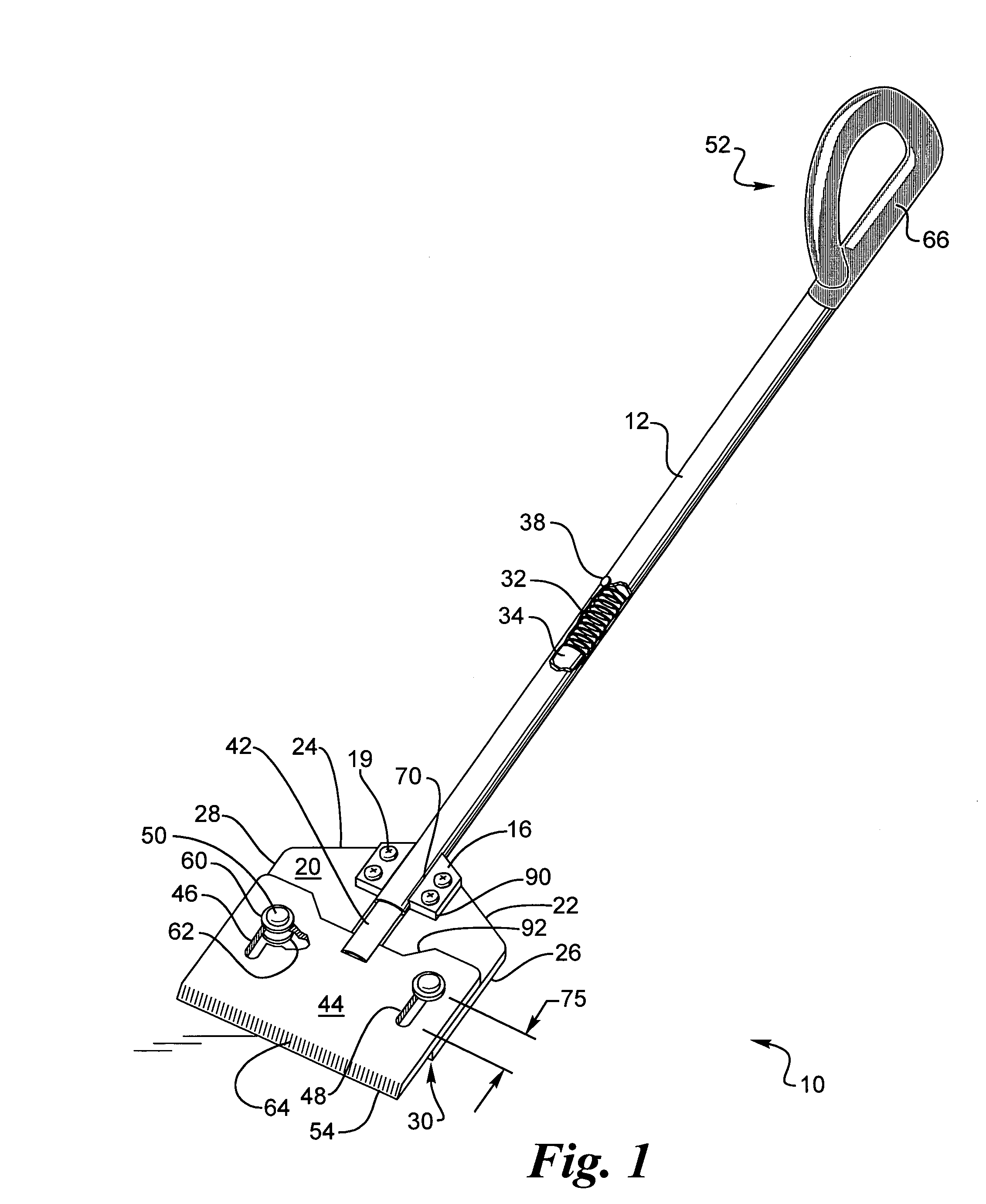
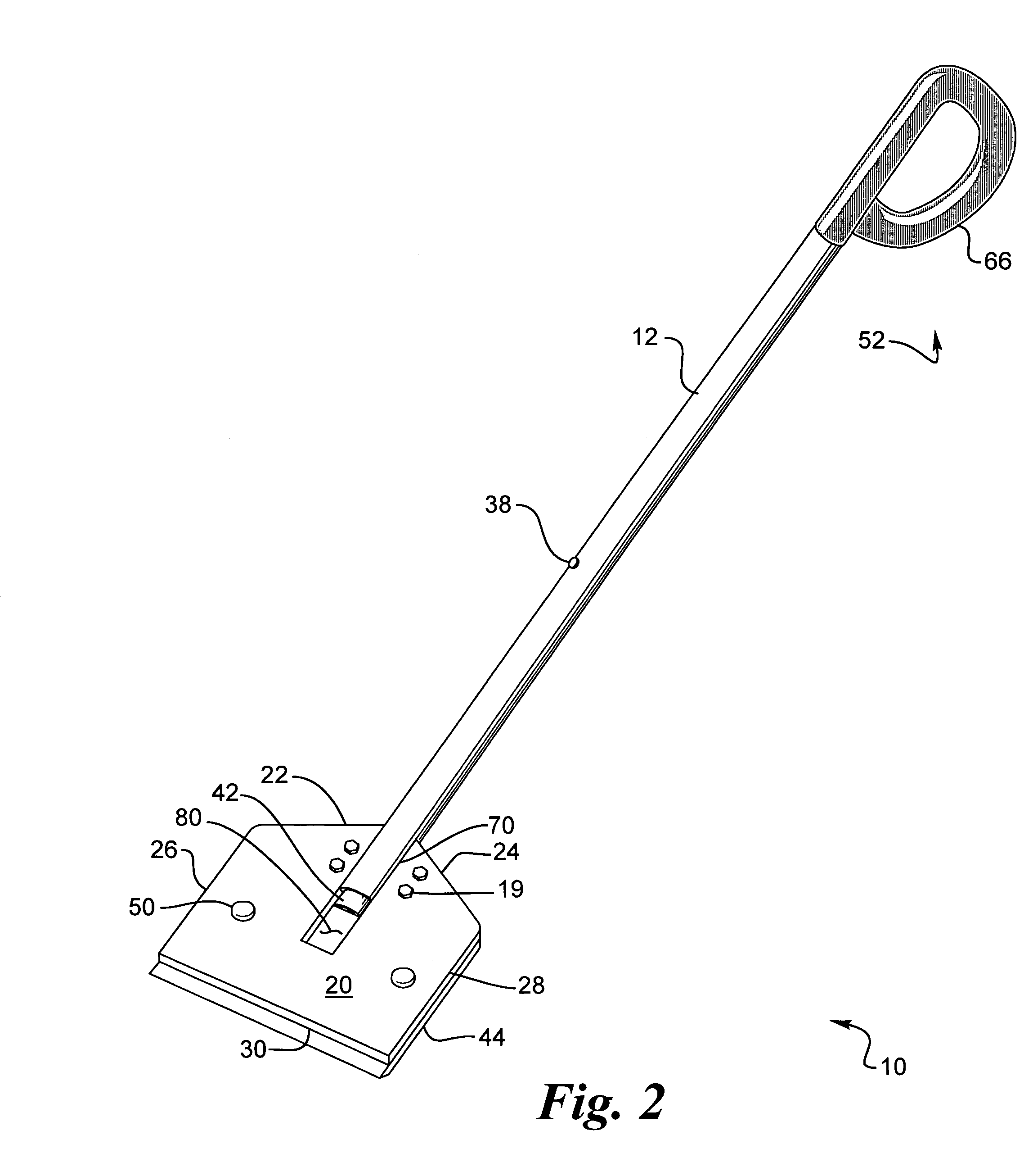
[0014]A preferred embodiment of the improved ice-chopping tool is indicated generally by numeral 10. It is seen to comprise an outer tubular handle member 12 and welded 70 to its outer surface proximate the distal end 14 thereof is a bracket 16 having a plurality of bolt receiving holes 18 extending through it. Affixed by fasteners such as bolts or rivets 19 to the bracket 16 is a first blade member 20, here shown as a polygon having first and second sloped top edges 22 and 24, opposed side edges 26 and 28 and a bottom edge 30. First blade member 20 has a slot 80 at the top center for allowing tube or rod 36 to move up and down without interference. While the blade 20 is shown as being attached by fasteners such as bolts 19 through apertures 58 to a bracket 16 welded 70 to the outer tubular handle 12, it is also envisioned that the blade member 20 may be directly welded to or otherwise affixed proximate the distal end 14 of the handle 12 Contained within the lumen of the outer tubul...


PUM

PropertyMeasurementUnit
Forceaaaaaaaaaa
Frictionaaaaaaaaaa

Abstract

An ice chopper having a blade for initially engaging ice with a small force followed by an impact of a larger force to break up the ice. The ice chopper has a tube for a handle having a second tube inside with a compression spring. The second tube has a blade attached, which engages ice and pushes the second tube up inside the tube simultaneously compressing the compression spring. When a stop is reached the second tube stops retracting and the impact force of the downward movement of the tube is absorbed by the blade for breaking the ice. The ice chopper is then lifted off the ice, the compression spring pushes the second tube and the blade downward and the ice chopper is ready for another stroke. An ergonomic handgrip is attached at the top of the tube for gripping the ice chopper.

Description

CROSS-REFERENCE TO RELATED APPLICATION[0001]This application claims priority under 35 U.S.C. 119(e) to U.S. Provisional Patent Application Ser. No. 60 / 569,350, filed May 7, 2004, entitled “HAND TOOL FOR CHOPPING ICE.”BACKGROUND OF THE INVENTION[0002]I. Field of the Invention[0003]This invention relates generally to yard tools, and more particularly to an improved hand tool for chopping ice from sidewalks and driveways.[0004]II. Discussion of the Prior Art[0005]During winter in colder climes, a problem arises when snow melts and then refreezes on driveways and sidewalks. Ice patches can be hazardous and are the cause of many slip and fall accidents. The melting and refreezing of snow creates ice patches that adhere strongly to the underlying concrete or asphalt surfaces of sidewalks and driveways.[0006]A typical prior art ice chopper comprises an elongated wooden handle having a sheet metal blade affixed to one end thereof where the blade may be trapezoidal in shape having a lower ed...

Claims


Application Information

Patent Timeline
IPC IPC(8): F25C5/00B25D3/00
CPCE01H5/02F25C5/043E01H5/12
Inventor MILLER, MICHAEL T.
Owner AMES TRUE TEMPER
Features
  • Generate Ideas
  • Intellectual Property
  • Life Sciences
  • Materials
  • Tech Scout
  • Unparalleled Data Quality
  • Higher Quality Content
  • 60% Fewer Hallucinations
Learn More