Hand tool comprising a dust suction device

a technology of dust suction device and hand tool, which is applied in the direction of manufacturing tools, percussive tools, portable power tools, etc., to achieve the effect of increasing vacuum

Inactive Publication Date: 2005-02-01
ROBERT BOSCH GMBH
View PDF8 Cites 49 Cited by
  • Summary
  • Abstract
  • Description
  • Claims
  • Application Information

AI Technical Summary

Benefits of technology

The stated object is attained by providing an air passage for the fan that supplies air to the fan when the fan produces an increased vacuum caused by the dust filter becoming clogged. Even when the dust filter is clogged, the fan can then still draw enough air via an additional air passage to cool the motor.

Problems solved by technology

Even when the dust filter is clogged, the fan can then still draw enough air via an additional air passage to cool the motor.

Method used


Image

  • Hand tool comprising a dust suction device
  • Hand tool comprising a dust suction device
  • Hand tool comprising a dust suction device

Examples


Embodiment Construction

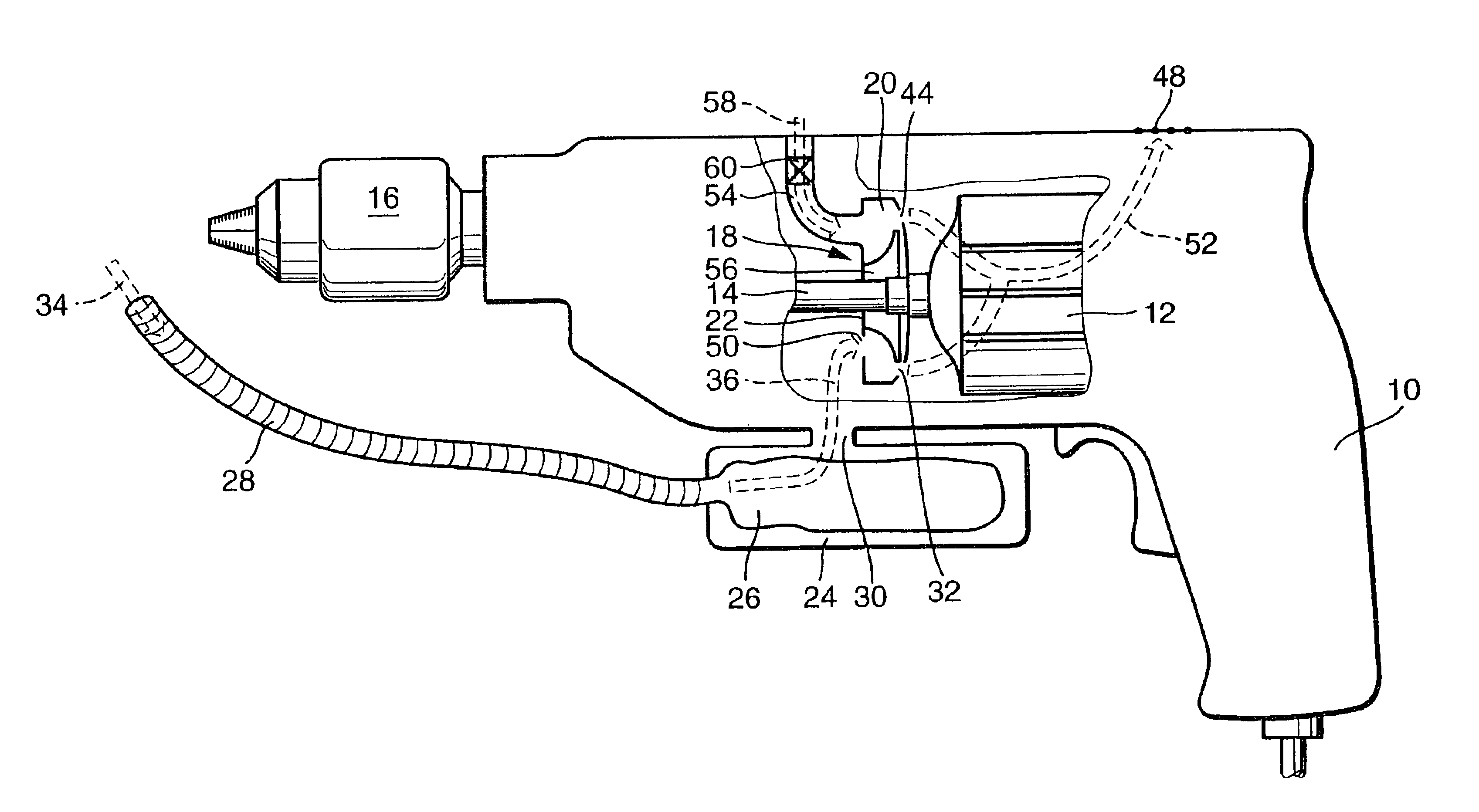
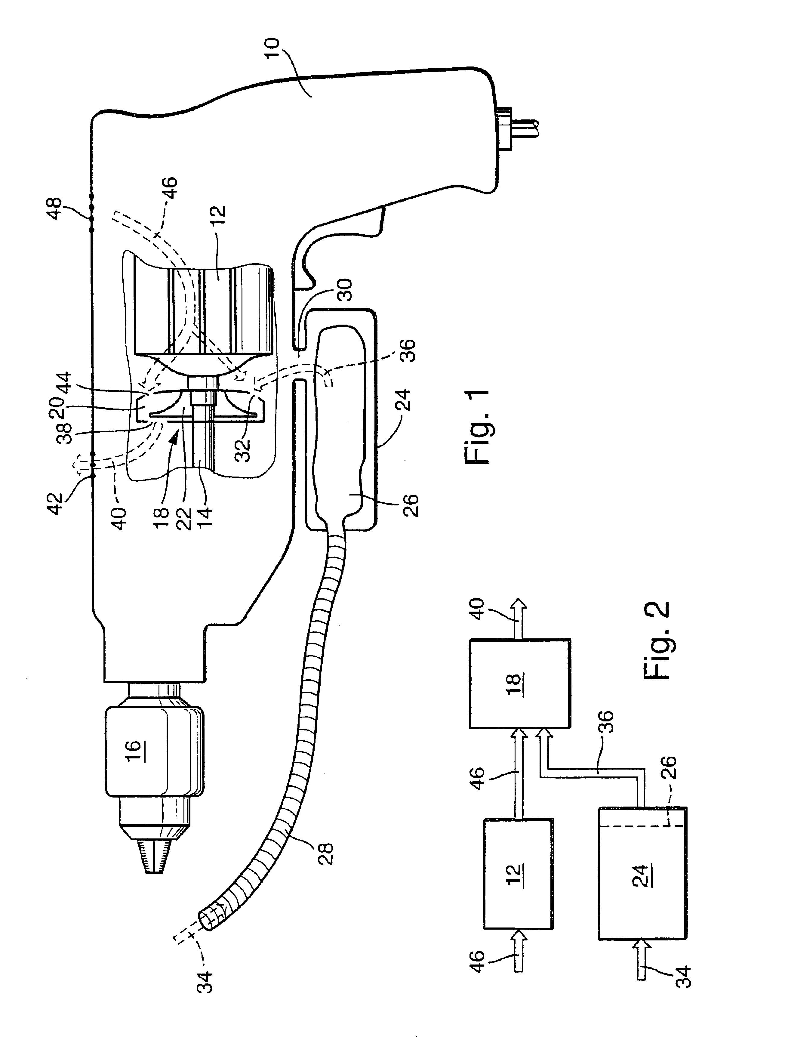
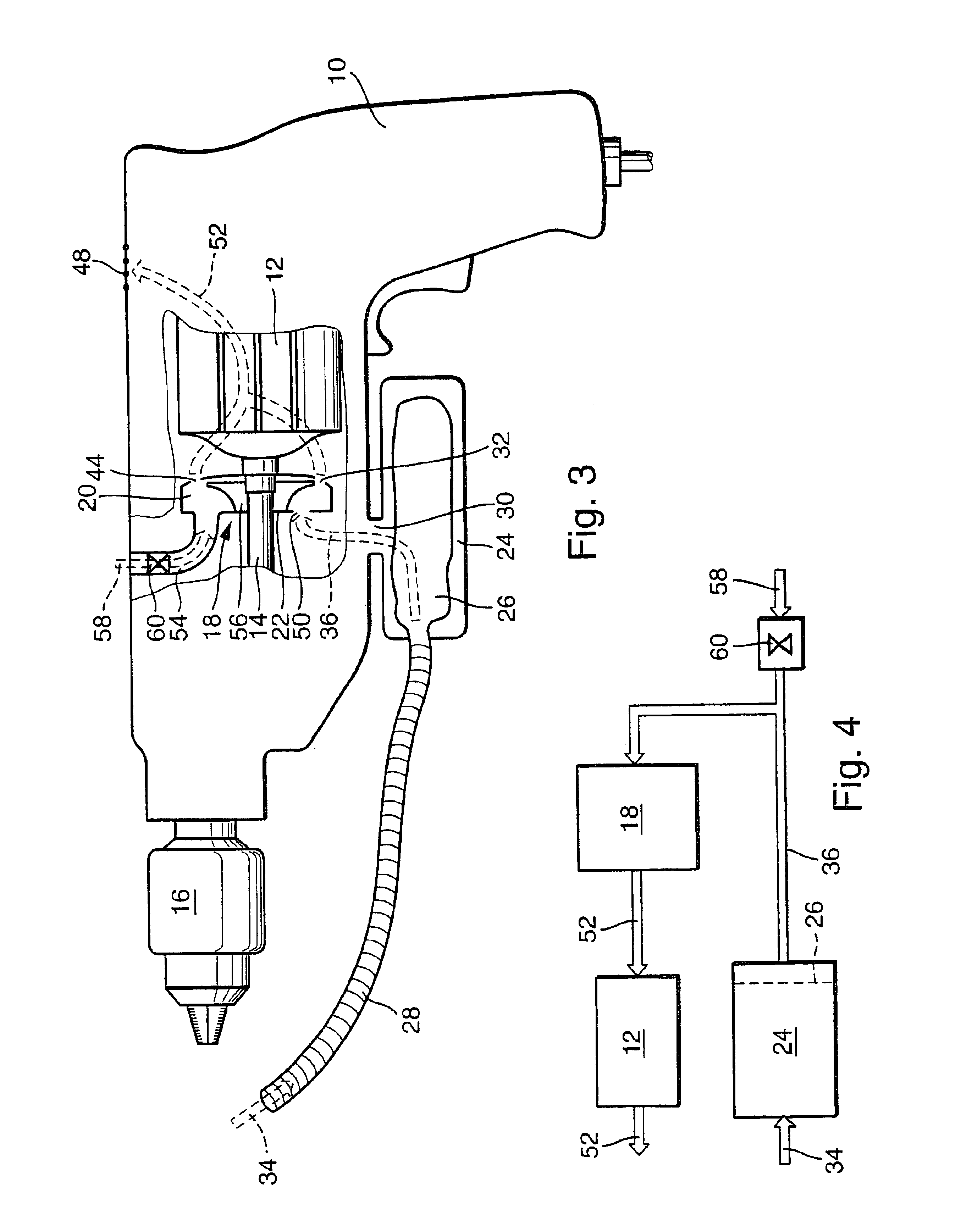
FIG. 1 is a partial sectional view of a hand power tool 10, e.g., a drilling hammer. The invention described hereinbelow concerns any type of hand power tool, however, that has a rotating drive and with which dust is produced when an object is machined.

As one can see through the cut-out in FIG. 1, a motor 12 is located in the hand power tool 10 that has a drive shaft 14 for a tool (not shown) mounted in a tool holder 16 of the hand power tool 10. A fan 18 is mounted on the drive shaft 14 that comprises a fan chamber 20 and a ventilator 22 that is located therein and is coupled with the drive shaft 14.

A dust collection receptacle 24 with a dust bag 26 functioning as dust filter is located on the outside of the power tool 10. A suction passage 28 empties into the dust collection receptacle 24 and / or into the dust bag 26, which said suction passage extends into the vicinity of the tool mounted in the hand power tool 10 where dust is produced while the hand power tool 10 is operated. An...


PUM

PropertyMeasurementUnit
vacuumaaaaaaaaaa
speedaaaaaaaaaa
rotational speedaaaaaaaaaa

Abstract

The dust removal device comprises a fan (18), a dust collection receptacle (24), and a suction passage (28). The dust collection receptacle (24) equipped with a dust filter (26) is located in the path of air flow (34, 36) between the suction passage (28) and the fan (18). The dust is therefore filtered out of the air stream before it reaches the fan, which prevents dust-induced wear. It is also possible to use the same fan for engine cooling as well as dust removal.

Description

BACKGROUND OF THE INVENTIONThe present invention concerns a hand power tool with a dust removal device, comprising a fan driven by the motor of the hand power tool, a dust collection receptacle, and a suction passage, whereby a path of air flow exists between the fan, the suction passage, and the dust collection receptacle such that air is drawn through the suction passage by the fan and is conveyed into the suctioned dust collection receptacle, whereby the dust collection receptacle equipped with the dust filter is located in the oath of air flow between the suction passage and the fan.A hand power tool with a dust removal device of this type was made known in DE 196 53 330 A1. With this arrangement of the dust collection receptacle between the suction passage and the fan-unlike the dust removal device made known, e.g., in DE 196 53 330 A1—the air filled with dust particles is not directed through the fan, because the fan can be damaged by the dust, which comes in at a relatively h...

Claims


Application Information

Patent Timeline
Patent Type & Authority Patents(United States)
IPC IPC(8): B23Q11/00B25F5/00B25D17/18
CPCB23Q11/0046B25F5/00Y10T408/50B23Q11/127
Inventor LAMPRECHT, JUSTUSHECHT, JOACHIMJONAS, STEPHAN
Owner ROBERT BOSCH GMBH
Why Eureka
Try Eureka