Vacuum heating and cooling apparatus

a technology of heating and cooling apparatus and vacuum chamber, which is applied in the field of vacuum heating and cooling apparatus, can solve the problems of deteriorating the reproducibility of heating step and cooling step, and achieve the effects of stable heating and cooling substrate, good reproducibility, and suppressing the temperature rise of the member

Inactive Publication Date: 2011-10-20
CANON ANELVA CORP
View PDF6 Cites 30 Cited by
  • Summary
  • Abstract
  • Description
  • Claims
  • Application Information

AI Technical Summary

Benefits of technology

[0028]The present invention has been made in view of the above problem, and an object thereof is to provide a vacuum heating and cooling apparatus which can conduct rapid heating and rapid cooling of substrate while maintaining high vacuum and can suppress the temperature rise of member in the vacuum chamber with time.
[0030]The present invention suppresses the temperature rise of the members in the vacuum chamber with time, thus allowing stable heating and cooling the substrates with good reproducibility therebetween even when successive heating and cooling treatments are given.

Problems solved by technology

Execution of both heating step and cooling step in the same vacuum chamber raises a problem of increase in the temperature of members in the chamber with increase in the number of treating substrates owing to the irradiation of heating light to the member in the chamber at every heating step, thus deteriorating the reproducibility of heating step and cooling step.

Method used


Image

  • Vacuum heating and cooling apparatus
  • Vacuum heating and cooling apparatus
  • Vacuum heating and cooling apparatus

Examples


first embodiment

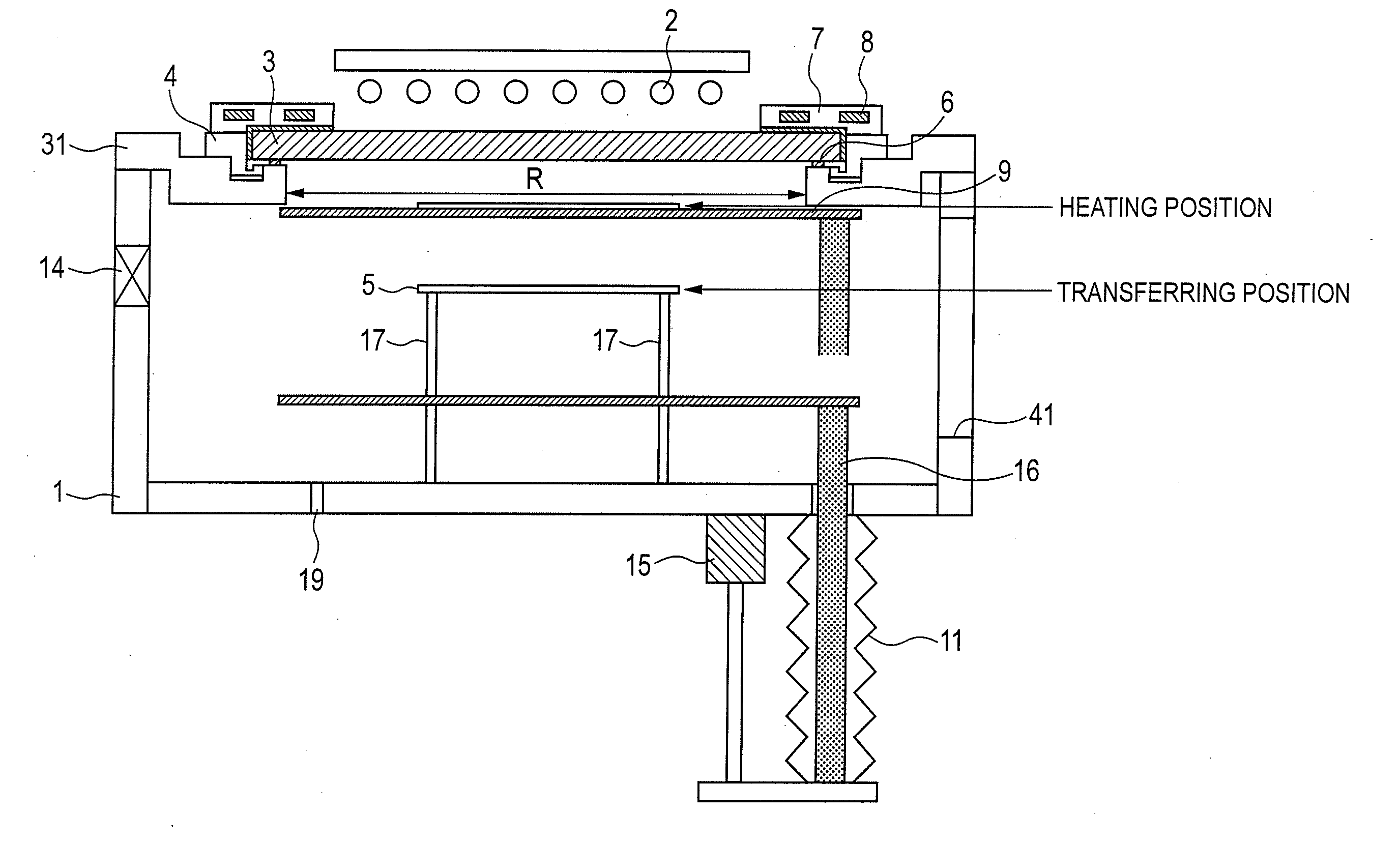
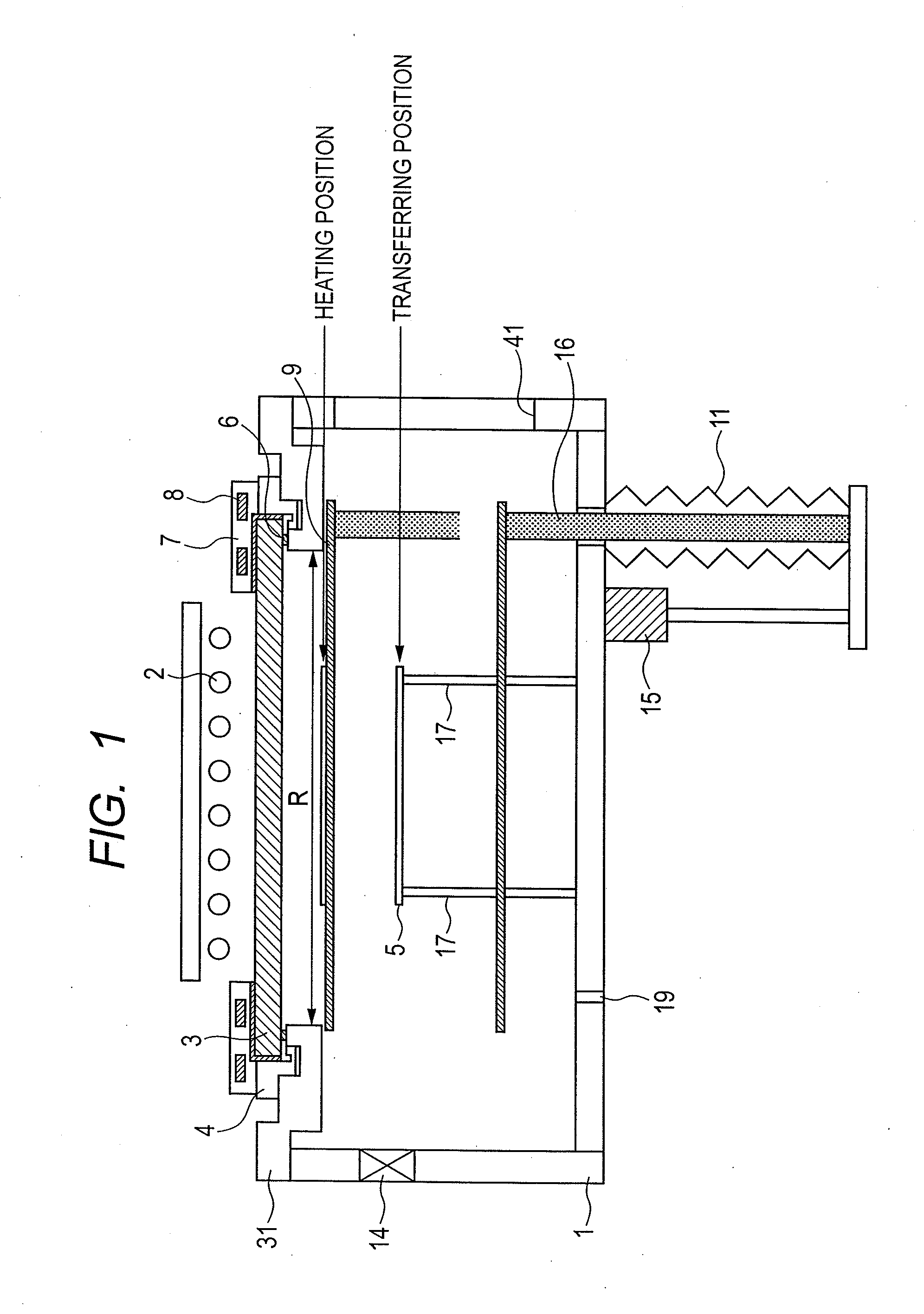
[0067]FIG. 1 illustrates the structure of vacuum heating and cooling apparatus according to the first embodiment.

[0068]In FIG. 1, a vacuum chamber 1 has a quartz window 3 fixed thereto at upper portion thereof using a vacuum-seal member (not shown), the window 3 allowing heating light coming from a halogen lamp 2 to penetrate therethrough. The vacuum-seal member is preferably a highly heat resistant O-ring such as Viton (trade mark) and Kalrez (trade mark). The quartz window 3 functions as an incidence part for causing the heating light generated from the halogen lamp 2 to enter the vacuum chamber 1. The outer shape R of the incidence part is, however, not defined by the outer shape of the quartz window 3, but is defined by the outer shape of the incidence part viewed from inside the vacuum chamber 1, or according to the example of FIG. 1, by the hole shape of a member 31 supporting the quartz window 3. As illustrated in FIG. 1, when a quartz window mounting and dismounting ring 4 i...

second embodiment

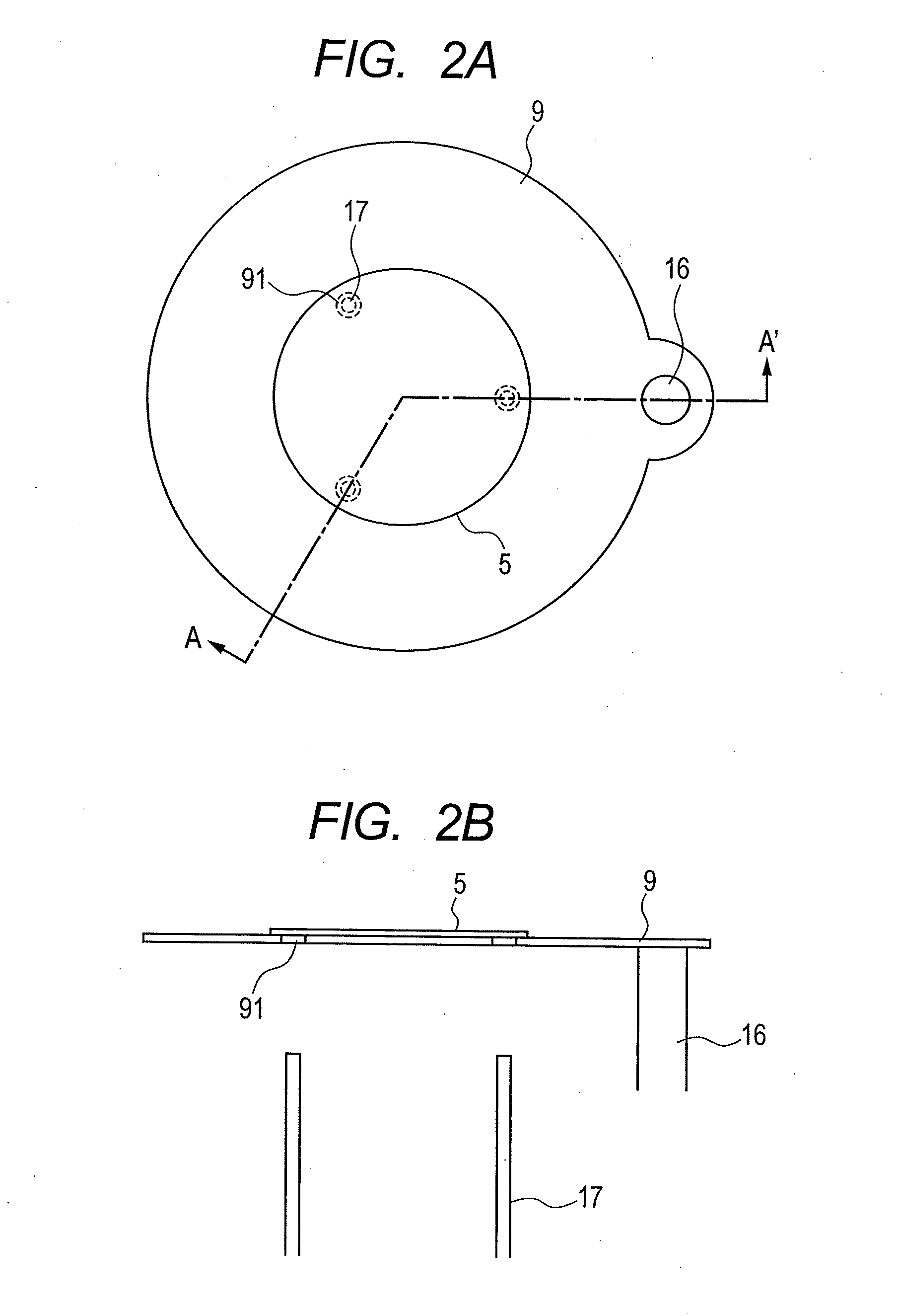
[0086]According to the first embodiment, the temperature of substrate 5 and substrate-holding member 9 after the heat treatment decreases naturally with time. However, a long time may be required to reach the room temperature level. Regarding the substrate, it can be carried-out at a high temperature. For the substrate-holding member 9, however, when a next substrate is carried-in while the temperature of the substrate-holding member 9 is not sufficiently decreased, the thermal conduction from the substrate-holding member 9 may vary the initial temperature of the substrate before the irradiation with the heating light. For the case of successive heat treatment of substrate, the effect of accumulation of heat with time in the substrate-holding member 9 induces temperature variation among substrates, which may result in poor production yield. To prevent or decrease the accumulation of heat with time in the substrate-holding member 9, in the second embodiment, a cooling member 10 is po...

third embodiment

[0094]During cooling step of the second embodiment, the substrate 5 is indirectly cooled by the cooling member 10 via the substrate-holding member 9. According to the third embodiment, for further increasing the cooling speed of the substrate, the substrate 5 is contacted with and placed directly on the cooling member 10 in the cooling step. Hence, the cooling speed can be increased. As illustrated in FIG. 15, the substrate-holding member 9 is in a ring-shape, the outer peripheral part of the substrate 5 is supported by the inner peripheral part of the ring-shaped substrate-holding member 9, and further the diameter of the cooling member 10 is designed to be smaller than the inner diameter of the ring-shaped substrate-holding member 9. More specifically, the inner diameter of the ring-shaped substrate-holding member 9 is set to 196 mm with respect to the diameter of 200 mm of the substrate, thus holding the substrate in a domain of 2 mm of the edge part of the inner peripheral part....


PUM

PropertyMeasurementUnit
magnetic fieldaaaaaaaaaa
diameteraaaaaaaaaa
diameteraaaaaaaaaa

Abstract

The vacuum heating and cooling apparatus can rapidly heat and cool only the substrate after film-forming treatment while maintaining high vacuum. The temperature rise of members in the chamber with time caused by accumulation of heat is suppressed, and the variation of temperature between substrates is decreased. In an embodiment, the heating and cooling apparatus for heating and cooling a substrate in a vacuum, includes: a vacuum chamber; a radiation energy source positioned at the vacuum chamber on an atmosphere side for emitting a heating light; an incidence part for causing the heating light from the radiation energy source to enter the vacuum chamber; a substrate-holding member for holding the substrate; and a substrate-transfer mechanism for transferring the substrate held by the substrate-holding member in a heating state to a heating position proximal to the radiation energy source, and transferring the substrate and the substrate-holding member in a non-heating state to a non-heating position distant from the radiation energy source, wherein the substrate-holding member has a plate shape for placing the substrate thereon and has an outer shape larger than that of the incidence part for causing the heating light to enter the vacuum chamber.

Description

CROSS-REFERENCES TO RELATED APPLICATIONS[0001]This application is a continuation application of International Application No. PCT / JP2010 / 067873, filed Oct. 12, 2010, which claims the benefit of Japanese Patent Application No. 2009-234927, filed Oct. 9, 2009. The contents of the aforementioned applications are incorporated herein by reference in their entities.TECHNICAL FIELD[0002]The present invention relates to a vacuum heating and cooling apparatus which rapidly heats and cools a substrate for a semiconductor device, an electronic device, a magnetic device, a display device, and the like in vacuum.BACKGROUND ART[0003]A tunnel magnetoresistance element having an MgO tunnel barrier layer, used as a sensor element of a magnetic random access memory (MRAM) and a magnetic head has a structure of laminating a plurality of metal films (magnetic film and non-magnetic film) and insulating films (such as MgO tunnel barrier layer). That type of magnetoresistance element is deposited by sputt...

Claims


Application Information

Patent Timeline
Patent Type & Authority Applications(United States)
IPC IPC(8): F27D11/12H01L21/00B05C11/00C23C14/56B05C9/14
CPCH01L21/67109H01L21/68742H01L21/67748H01L21/67115C23C14/541G11C11/16H01L21/324G11C11/15
Inventor TSUNEKAWA, KOJINAGAMINE, YOSHINORISUZUKI, NAOYUKIOKADA, TAKUJIINABA, SHINICHI
Owner CANON ANELVA CORP
Why Eureka
Try Eureka