

Methods for attaching an elastomeric sleeve to an elongate article
a technology of elastomeric sleeves and elongated articles, which is applied in the direction of wing knobs, rigid containers, wing handles, etc., can solve the problems of reducing the service life of the elastomeric sleeves
- Summary
- Abstract
- Description
- Claims
- Application Information
AI Technical Summary
Benefits of technology
Problems solved by technology
Method used
Image

Examples
example two
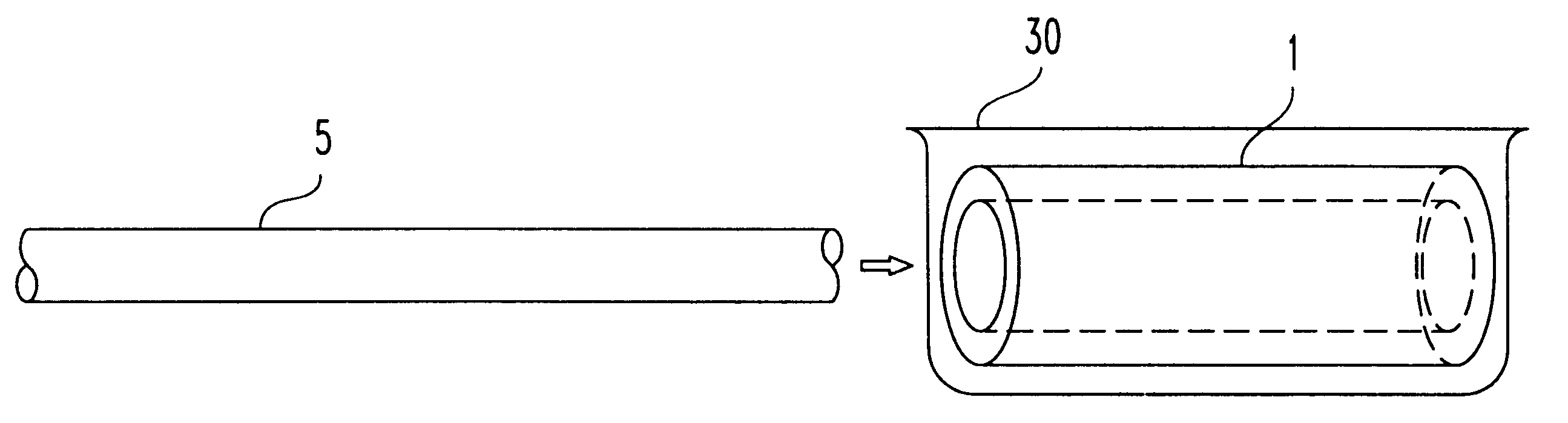
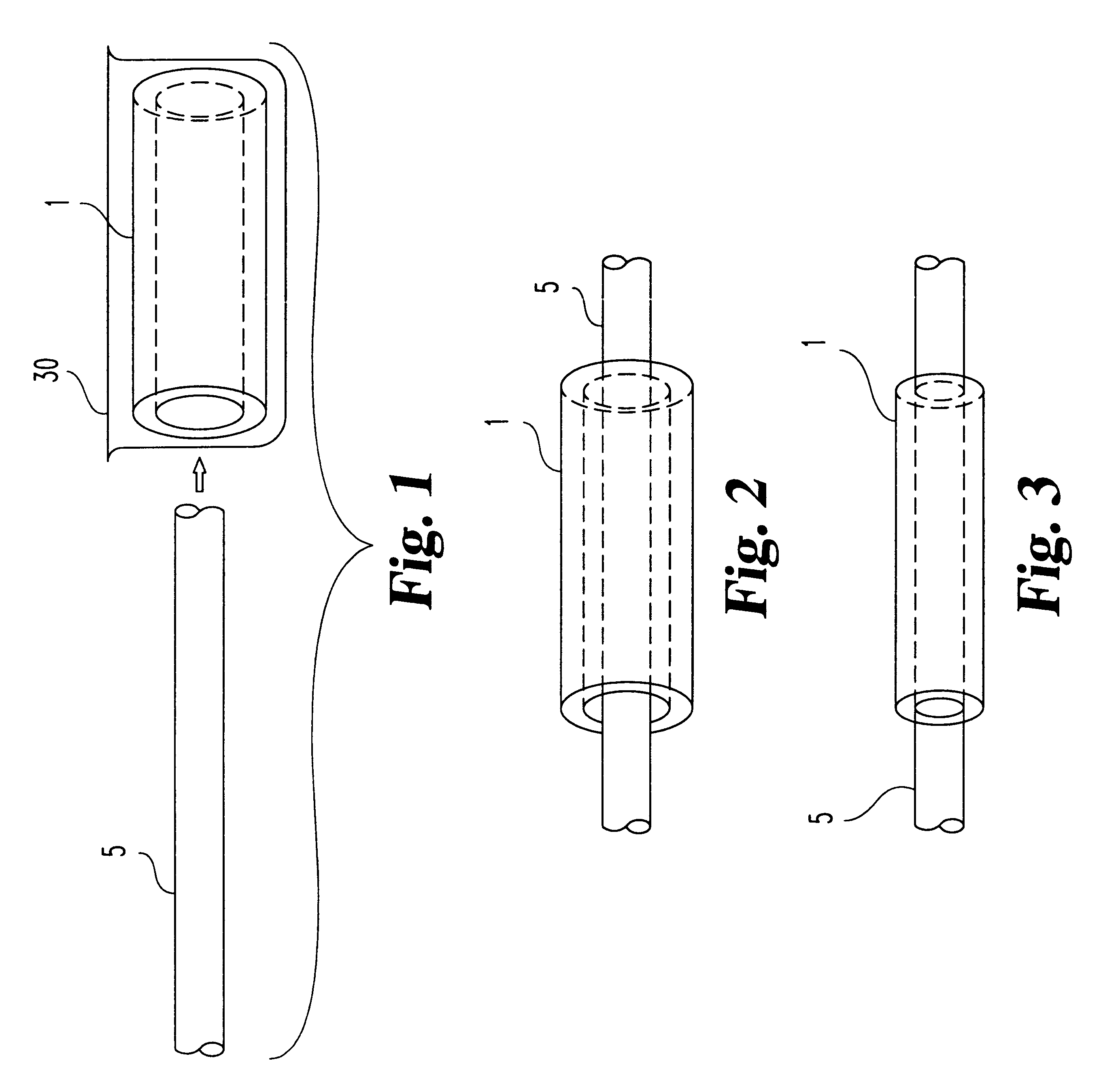
Making An Inventive Sleeve
The procedures of Example 1 is followed except that the swelling solvent is prepared by combining about 80.0% of ISOPAR C.RTM., about 5.0% of ISOPAR E.RTM., about 7.0% of a polybutene and about 8.0% of a fluorocarbon and mixing.
example three
Making An Inventive Sleeve
A swelling solvent is made by combining about 80% of cyclononane and about 20% of a fluorocarbon and mixing. A preformed, substantially tubular sleeve, comprising about 52% ethylene propylene diene monomer ("EPDM") is contacted with the swelling solvent in a ratio of about 0.9:1 solvent:elastomeric material by weight to provide an expanded sleeve. The expanded sleeve having solvent absorbed therein is then maintained in an airtight container in a substantial vacuum, thereby preventing the solvent from evaporating from the sleeve.
example four
Making An Inventive Sleeve
The procedure of Example 3 is followed except that the swelling solvent is made by combining about 77% of cyclononane, about 20% of a fluorocarbon, and about 3% of a polybutene and mixing.
PUM
| Property | Measurement | Unit |
|---|---|---|
| Elastomeric | aaaaa | aaaaa |
| Weight ratio | aaaaa | aaaaa |
| Dimension | aaaaa | aaaaa |
Abstract
Description
Claims
Application Information