Buckling opposing support for I-joist
a technology of supporting device and joist, which is applied in the direction of joists, girders, building repairs, etc., can solve the problems of buckling tendency, inability to meet construction standards, and often compromised structural integrity of the web, so as to increase the stiffness of the device, increase the interlocking effect, and ensure the effect of attachmen
- Summary
- Abstract
- Description
- Claims
- Application Information
AI Technical Summary
Benefits of technology
Problems solved by technology
Method used
Image
Examples
first embodiment
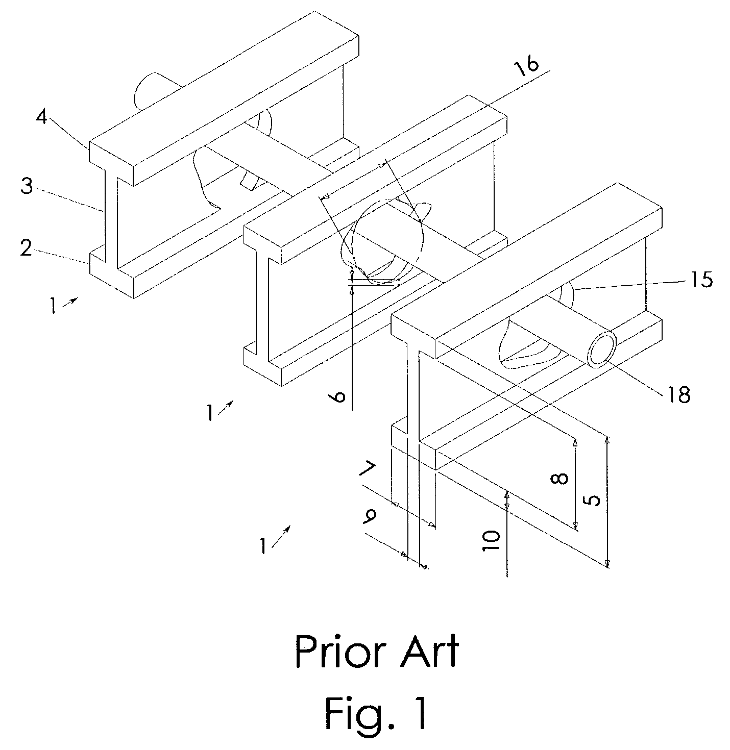
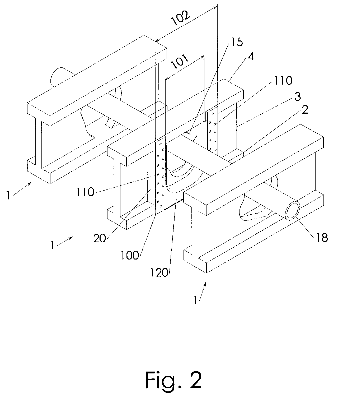
[0040]The support device 100 provides bridging structures 110 that spans across the web height 8 with its central portion. The bridging structures 110 establish with their central portion a buckling opposing interface with the web 3 once attached to the web 3. By placing a bridging structure 110 of the first embodiment immediately adjacent the erroneously cut hole 15 and combining it with the additional support structure 20, the unpredictable buckling tendency of the I-joist 1 in the vicinity of the erroneously cut hole 15 is brought within predictable limits.
[0041]In the context of the present invention the terms “top”, “bottom”, “horizontal”, “vertical” are introduced in reference to an assembly position of the support device 100 on an I-joist 1 in a conventional assembly position with one chord above the other, where the I-joist 1 may have its maximum load carrying capacity.
[0042]A buckling opposing interface is-defined by contacting the remainder of the web 3 with the central po...
third embodiment
[0054]In FIG. 6, a third of the preferred embodiments is illustrated, in which third stiffening ribs 150 protrude from the outer edge of one or both of the bridging structures 110. The third stiffening ribs 150 protrude in direction substantially parallel to the first stiffening rib 130 and may be of substantially equal height as the first stiffening rib 130. The third stiffening ribs 150 provide additional bending stiffness to the central portion of the bridging structures 110. The third stiffening ribs 150 may be in a distance to a vertical portion of the first stiffening rib 130 such that the support structure 20 may be snuggly held between them. This may additionally ease the assembly process, since the support structure 20 may be brought into position relative to the support device 100 prior to assembly of the support device 100 itself. A support device 100 in accordance with the third embodiment is shown in top view in FIG. 13A, in perspective view in FIG. 13B, in side view wh...
fifth embodiment
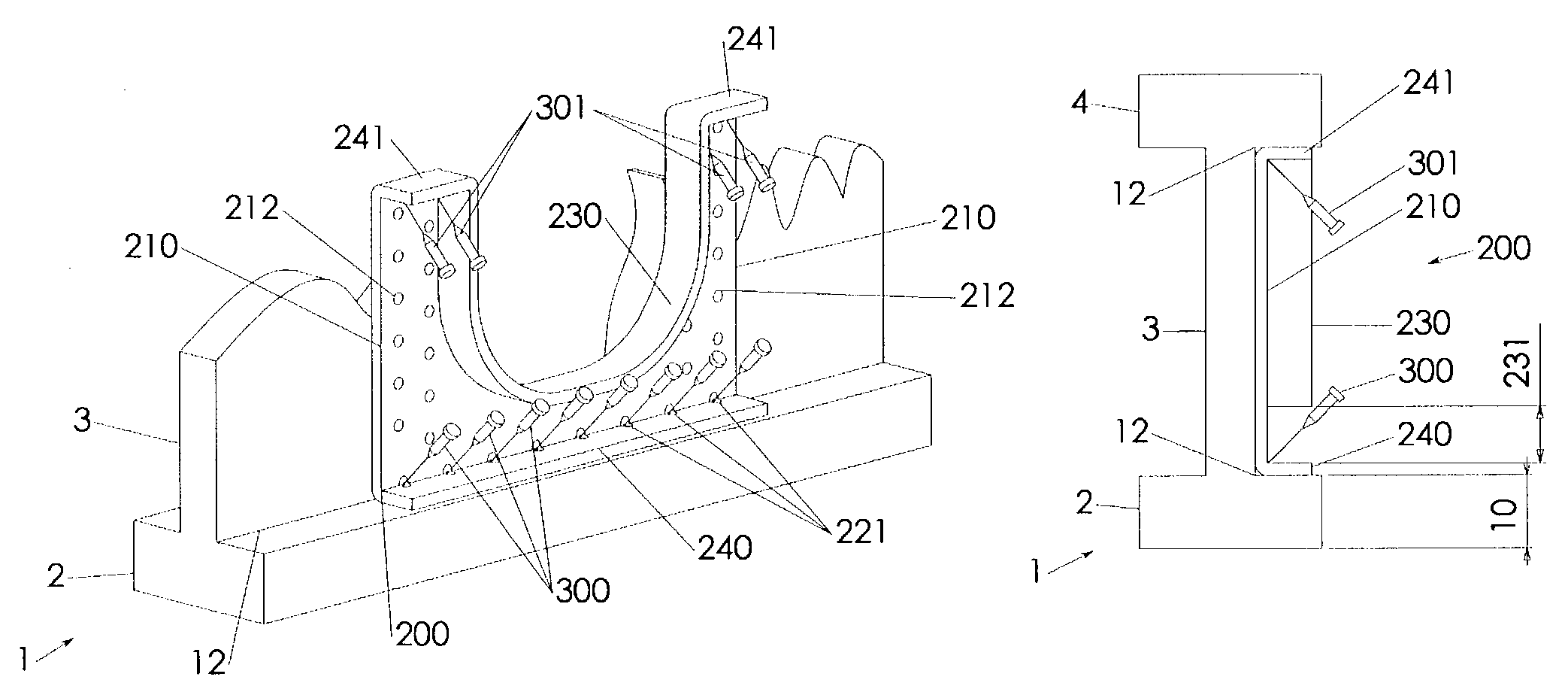
[0064]The bridging structures 210 are directly attached to the web 3 via primary attachment holes 212. The bridging structures 210 operate similar like bridging structures 110 except that they provide the buckling opposing interface with the remainder of the web 3 without inclusion of the support structure 20. A support device 200 in accordance with the fifth embodiment is shown in top view in FIG. 15A, in perspective view in FIG. 15B, in side view which is in protrusion direction of the I-joist 1 in FIG. 15C, and in FIG. 15D in front view, which is in direction of the reference plane 11.
PUM
 Abstract
Description
Claims
Application Information
 - R&D
- Intellectual Property
- Life Sciences
- Materials
- Tech Scout
- Unparalleled Data Quality
- Higher Quality Content
- 60% Fewer Hallucinations
Browse by: Latest US Patents, China's latest patents, Technical Efficacy Thesaurus, Application Domain, Technology Topic, Popular Technical Reports.
© 2025 PatSnap. All rights reserved.Legal|Privacy policy|Modern Slavery Act Transparency Statement|Sitemap|About US| Contact US: help@patsnap.com


