Mooring system with active control

a mooring system and active control technology, applied in the field of mooring systems with active control, can solve the problems of inability to provide mooring load data, inability to mooring a vacuum cup-style mooring robot, and mooring lines are often elastic in nature, so as to improve safety, reduce energy consumption, and improve the effect of performan

Inactive Publication Date: 2007-11-13
CAVOTEC MOORMASTER
View PDF28 Cites 24 Cited by
  • Summary
  • Abstract
  • Description
  • Claims
  • Application Information

AI Technical Summary

Benefits of technology

[0016]Accordingly in a first aspect the invention includes a method of controlling a vessel mooring system said system including at least one mooring robot for releasably fastening a vessel floating at the surface of a body of water to a terminal, the mooring robot including an attractive force attachment element displaceably engaged to a base structure of said mooring robot said base structure affixed to said terminal, said attractive force attachment element being releasably engagable with a vessel surface for making fast the vessel with said terminal, the mooring robot providing active translational movement of the attractive force attachment element relative to the base structure to allow thereby the movement of a vessel in a direction selected from any one or both of
[0034]Preferably said system included a plurality of spaced apart mooring robots, each presenting an attractive force attachment element to engage to a surface of said vessel, wherein said method further includes, when any one or more of the forces measured in (b) of one of said mooring robots tends toward allowing relative movement between the attractive force attachment element and the said vessel in a direction parallel to such force(s) measured by such approaching a holding capacity of the attractive force attachment element in any such direction, at least one of the other mooring robots is controlled for movement of its attractive force attachment element relative to said fixed base in a direction to vary the force between its attractive force attachment element and its base structure in a direction opposite to such said direction to thereby reduce the force in such said direction between the attractive force attachment element and its said base structure of said one mooring robot.
[0056]iii. a displacement of the attractive force attachment element of at least one other mooring robot relative to its base structure, in a direction opposite to the direction tending to allowing a relative movement between said vessel and said attractive force attachment element of said mooring robot, to increase the loading force on said at least one other mooring robot and reducing the loading force on the said mooring robot in said direction tending to allowing a relative movement between said vessel and said attractive force attachment element of said mooring robot.
[0069]Preferably wherein each mooring robot includes means to actuate translational movement of the attractive force attachment element relative to the base structure in at least an athwartship direction and wherein said means to control may in addition initiate a displacement of attractive force attachment element of an other robot of said system in the athwartship direction towards its said fixed structure thereby increasing the loading force of said other of said mooring robots dependent on such an other mooring robot having capacity determined from said attractive force capacity reading, to do so.
[0144]Controlling the operation of a mooring system according to the method of certain embodiments improves its performance, reduces energy consumption and improves safety. By providing an alarm as capacity is approached, together with feedback of the capacity and the magnitude and direction of the applied loads, it allows the master of the vessel to take the most appropriate action to ensure the safety of the vessel in extreme conditions.

Problems solved by technology

However, a problem which any mooring system must counter is the effect of water currents and wind which tend to apply forces to a ship in a direction which may encourage the ship out of contact with the mooring robots.
Failure in the mooring of a vessel with a vacuum cup style mooring robot occurs when the forces applied to a vessel in a direction tending to release the vessel from the vacuum cups exceed the suction force of the vacuum cups on the vessel.
Furthermore since there is no measurement of angles of force between the vessel and the mooring lines it is not possible to utilise the system of U.S. Pat. No. 4,055,137 to determine the total force being applied to the vessel in for example the athwartship direction and longitudinal direction.
The system of U.S. Pat. No. 4,055,137 is also unable to provide mooring load data while the vessel is moving relative to the terminal, since the system is not designed to purposefully move a ship.
A further issue in respect of the monitoring of forces and displacements in a mooring line mooring system is the fact that such mooring lines are often elastic in nature.
Whilst measurements of the mooring lines can be achieved to provide absolute information thereof, it is not an instantaneous reflection of the loading and position of the vessel.
Moreover the accuracy achievable with the mooring line prior art systems is limited by the properties of the mooring lines, which may interfere with one another or with bollards etc to produce anomalous effects which cannot be readily measured.

Method used


Image

  • Mooring system with active control
  • Mooring system with active control
  • Mooring system with active control

Examples


Embodiment Construction

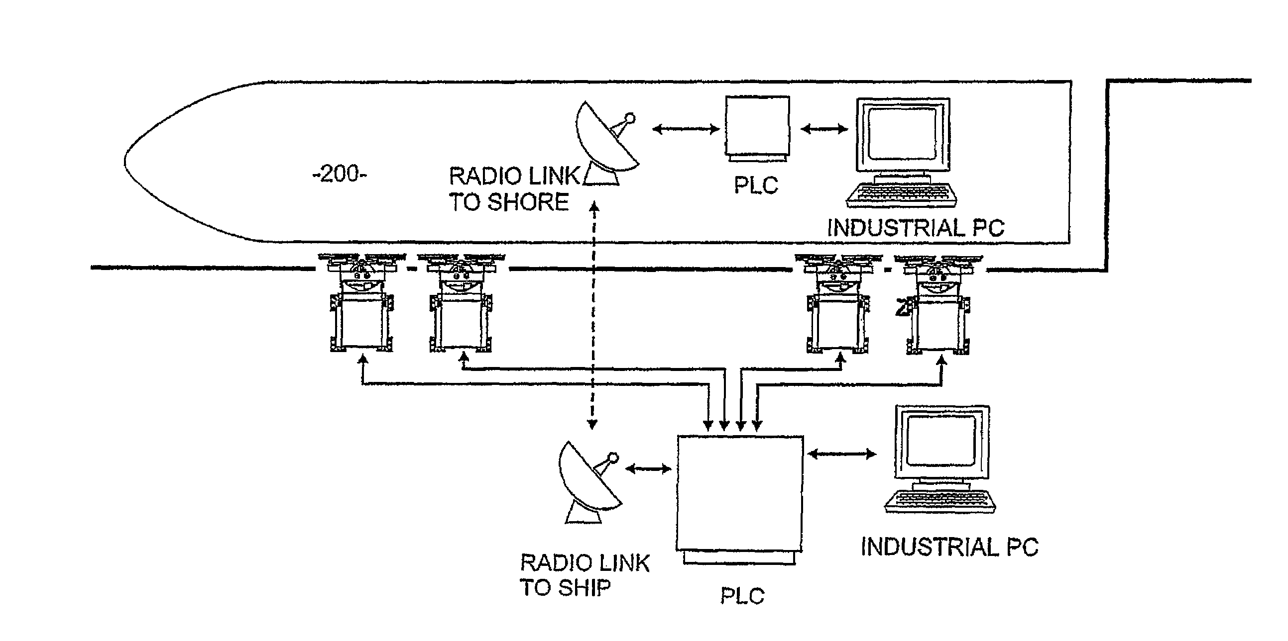
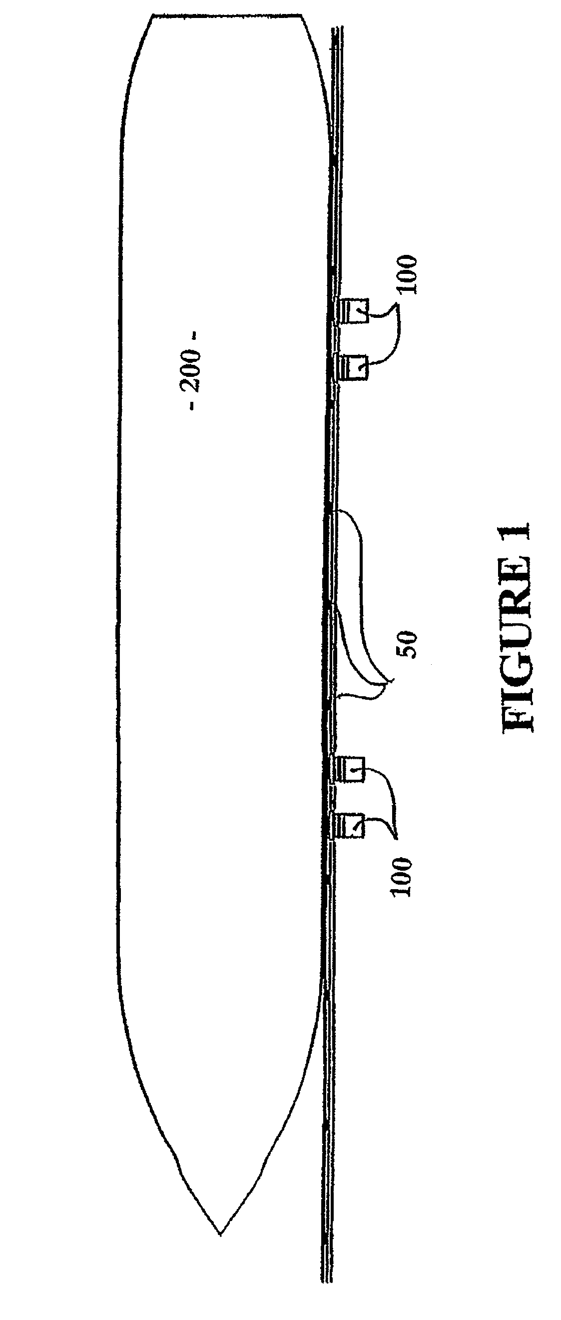
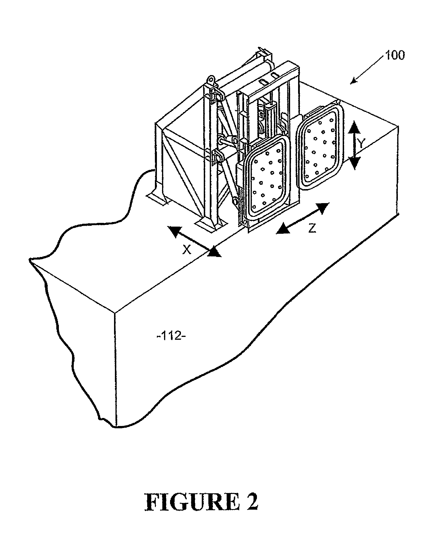
[0187]Referring to FIGS. 1, 2 and 3 of the drawings, the present invention comprises a mooring system incorporating at least one and in a more preferred form, a plurality of mooring robots 100, which may be of a kind described in our PCT International Application No. PCT / NZ02 / 00062. The description of the mooring robots in PCT / NZ02 / 00062 is hereby incorporated by reference. Other preferred embodiments of a mooring robot for the system of the present invention may also be utilised and reference will hereinafter be made to an alternative form with reference to FIGS. 19 to 21. The mooring system may alternatively include mooring robots 100 fixed to the vessel allowing the vessel to be readily fastened to a bearing plate fixed to the dock 110 or to another vessel. Whilst reference in the most preferred form of the invention is made to a configuration where a mooring robots is fixed on a wharf, it will be appreciated that such mooring robots may alternatively be engaged to fixed pylons o...


PUM


Abstract

A vessel mooring system which includes at least two mooring robots secured to a terminal, each robot includes an attractive force attachment element eg. a vacuum cup and a base structure fixed relative to the terminal. The attachment element is able to be engaged with a vertically extending side vessel surface and to exert an attractive force normal to the vessel surface at where it is to be attached. Each robot can measure the attractive force between the attachment element and the vessel to provide an “attractive force capacity reading”. Also provided is capability to measure the force between the attachment element and the fixed structure of the mooring robot to provide a “normal force reading”. From monitoring of the relationship between the attractive force capacity reading and the normal force a control of the mooring robot can be provided such that if there is a tending to separate the attachment elements from said vessel the attractive force may be increased and / or alarm is sounded.

Description

RELATED APPLICATIONS[0001]This application is a national phase entry in the United States of the International Application PCT / NZ2003 / 000167 filed Jul. 30, 2003 and claims the benefit of the New Zealand Application 520450 filed Jul. 30, 2002.BACKGROUND OF THE INVENTION[0002]1. Technical Field[0003]The present invention relates to a vessel mooring system with active control and more specifically to a system for monitoring mooring loads applied to and displacement of a vessel. In particular although not solely the invention relates to the control of a mooring system employing mooring robots having an attractive attachment element for engagement with a surface for making fast the ship.[0004]2. Background Art[0005]The mooring of a ship at a terminal such as a dock utilising mooring robots is known. Automated systems such as these are described for example in WO 0162585 and have a number of advantages over conventional methods of mooring employing mooring lines.[0006]When a ship is appro...

Claims


Application Information

Patent Timeline
Patent Type & Authority Patents(United States)
IPC IPC(8): B63B21/00E02B3/20
CPCB63B21/00E02B3/20B63B2021/006
Inventor MONTGOMERY, PETER JAMESROSSITER, BRYAN JOHN
Owner CAVOTEC MOORMASTER
Why Eureka
Try Eureka