Device for marking upon a surface

a technology for marking devices and surfaces, applied in writing aids, manufacturing tools, instruments, etc., can solve the problems of permanent staining of walls and multiple holes, and achieve the effect of convenient manipulation and us

Inactive Publication Date: 2007-11-13
CCN WORLD
View PDF4 Cites 34 Cited by
  • Summary
  • Abstract
  • Description
  • Claims
  • Application Information

AI Technical Summary

Benefits of technology

[0008]It is therefore one of the main objects of the present invention to provide a device for marking upon a surface that permits a user to mak...

Problems solved by technology

Making an incorrect mark upon the surface may result in multiple h...

Method used


Image

  • Device for marking upon a surface
  • Device for marking upon a surface
  • Device for marking upon a surface

Examples


Embodiment Construction

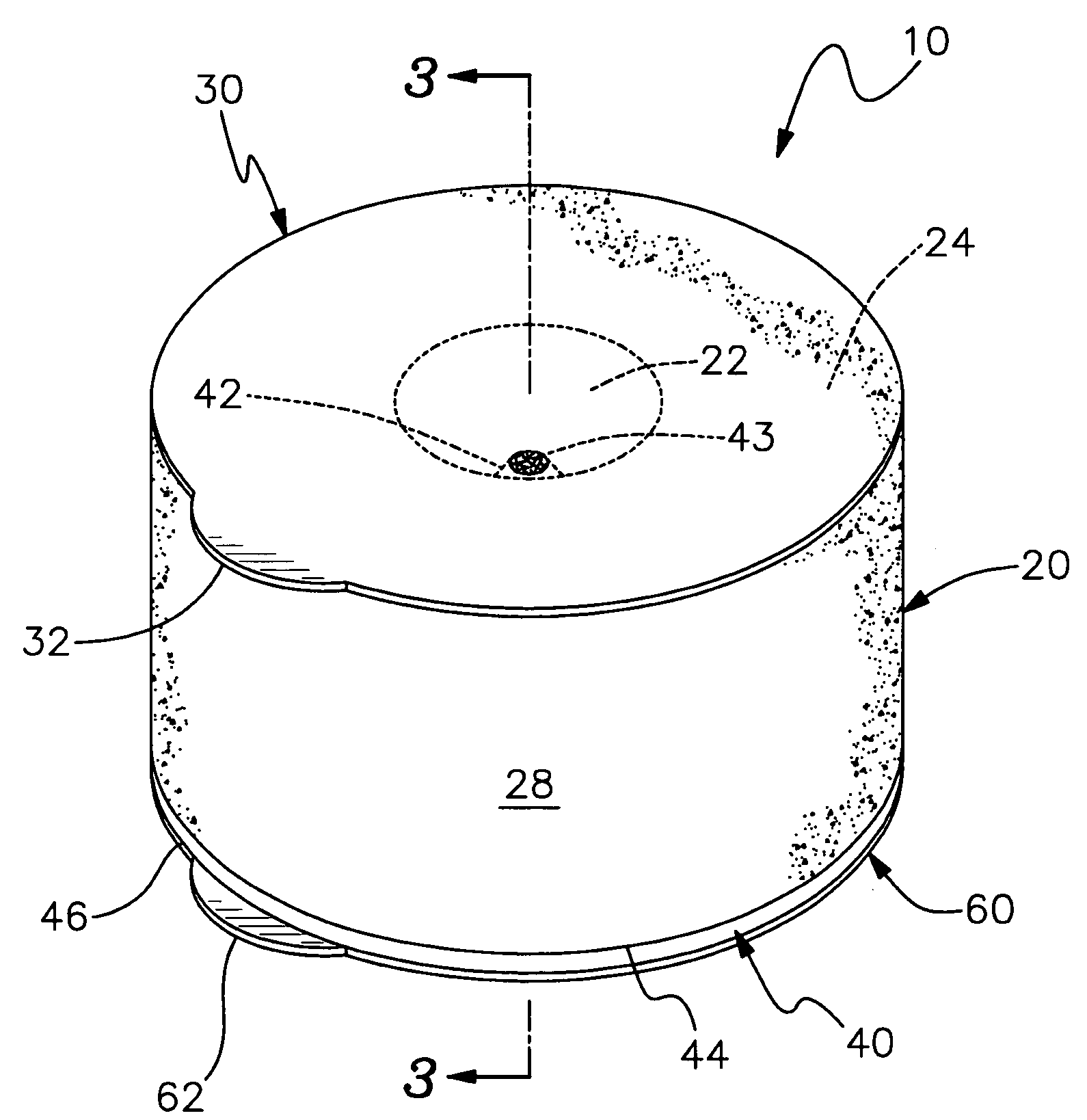
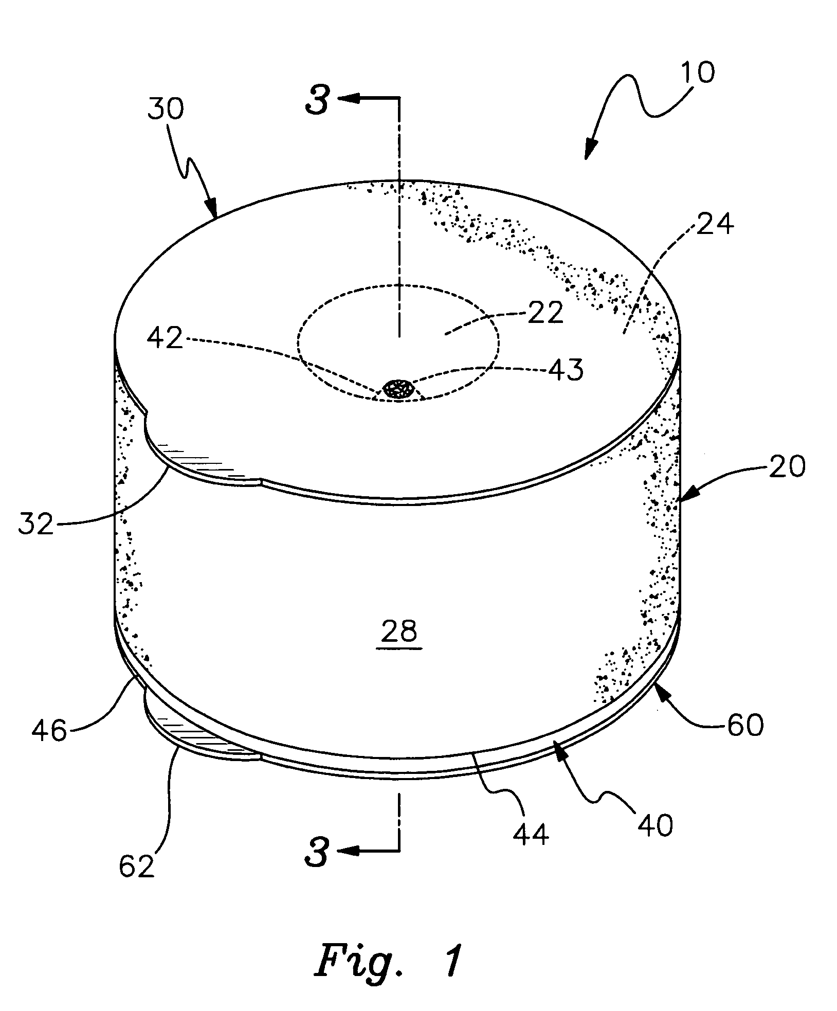
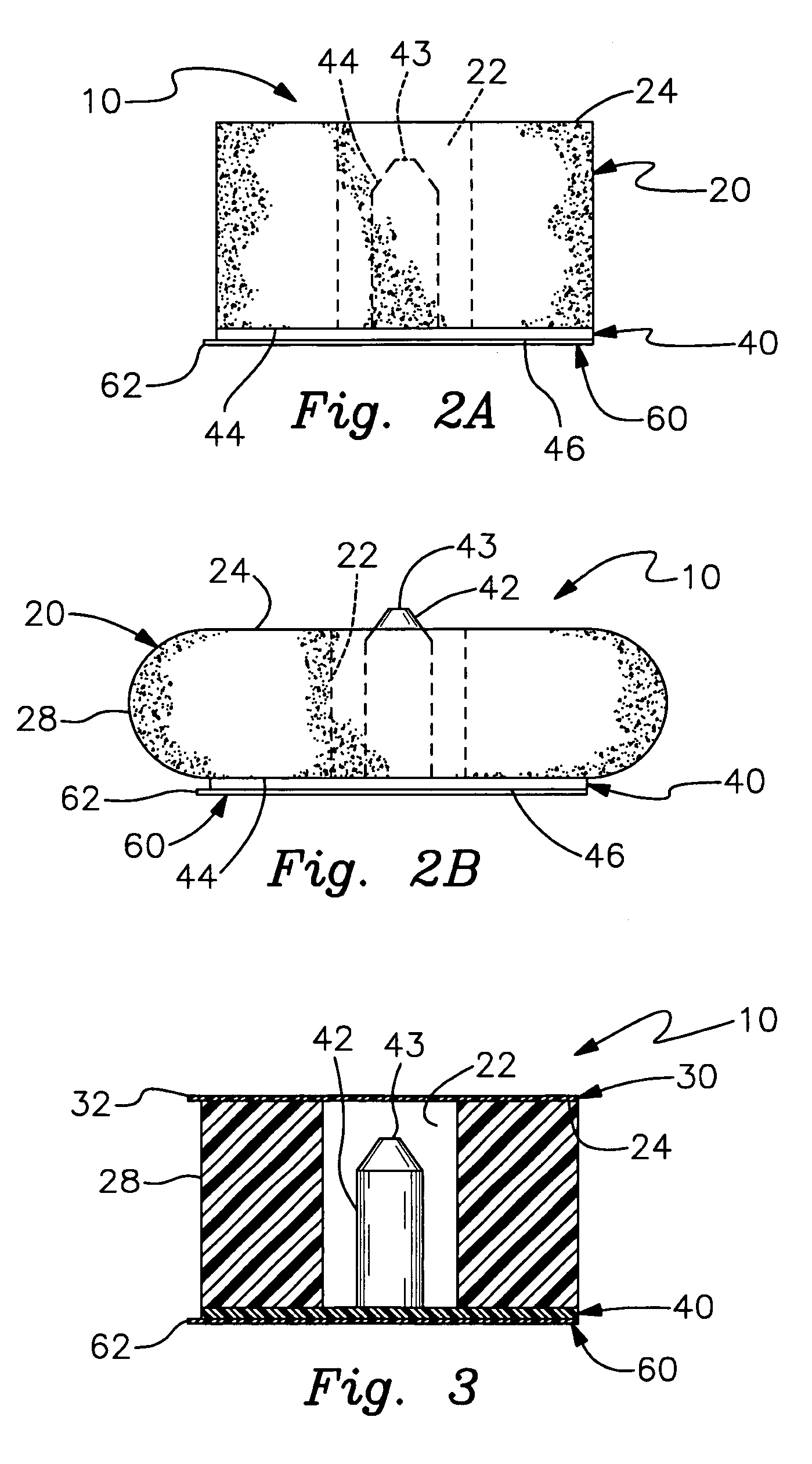
[0021]Referring now to the drawings, where the present invention is defined as a device for marking upon a surface and is generally referred to with numeral 10, it can be observed that it basically includes body assembly 20, cover member 30, base assembly 40, and bottom cover member 60.

[0022]As seen in FIGS. 1; 2A; and 3, body assembly 20 is made of a soft resilient material, such as foam. In the preferred embodiment, body assembly 20 has a cylindrical shape and comprises central opening 22, upper end 24, and outer circular wall 28. Cover member 30 is removably mounted to upper end 24. Upper end 24 has adhesive properties. Cover member 30 protects upper end 24 and central opening 22 when device for marking 10 is not in use. Cover member 30 has tab member 32 to facilitate the user to remove it when needed. Furthermore, cover member 30 prevents marker 42 from drying out when instant invention 10 is not in use. Base assembly 40 has a cooperative shape and dimension to cover the bottom ...


PUM


Abstract

A device for marking upon a surface including a body assembly made of a resilient material, a cover member, a base assembly and a bottom cover. The body assembly has an outer wall, a central opening an upper end and a bottom end. The base assembly includes a marker rigidly attached to the center of the upper surface and a bottom surface. The upper surface is fixedly secure upon the bottom end of the body assembly in a way that the marker is housed within central opening. The bottom cover protects bottom surface. Cover member protects the upper end and the opening of the body assembly and prevents the marker from drying when the device for marking is not in use.

Description

BACKGROUND OF THE INVENTION[0001]1. Field of the Invention[0002]The present invention relates to a device for marking, and more particularly, to a device for marking upon a surface such as a wall.[0003]2. Description of the Related Art[0004]When hanging a frame for a painting or mirror, it is often necessary to make a mark upon a surface to position where a nail and / or wall anchor will be placed. Making an incorrect mark upon the surface may result in multiple holes being made into a wall, or may otherwise permanently stain the wall. There is a need for a device that marks upon a surface, that is accurate and easy to use, to hang frames for paintings, mirrors, and the like.[0005]There are no devices for marking upon a surface to the best of applicant's knowledge that include a body assembly made of a soft resilient material with a central opening, and a base assembly with a marker rigidly attached to its center in a way that the marker is housed within the central opening.SUMMARY OF...

Claims


Application Information

Patent Timeline
IPC IPC(8): A46B11/00B25H7/00B43K23/00B43K5/00G01D21/00
CPCA47G1/205B25H7/02B43L12/00B43K23/08B43K23/001
Inventor SANSEVIERO, NICOLAS
Owner CCN WORLD
Why Eureka
Try Eureka