Flying disc

a technology of flying discs and discs, which is applied in the direction of vertical landing/take-off aircraft, aircraft navigation control, sport apparatus, etc., can solve the problems of affecting the angle of attack, affecting the downwash, and causing drag, so as to improve the flight efficiency and increase the flight distan

Inactive Publication Date: 2007-11-13
POTTS JONATHAN
View PDF19 Cites 7 Cited by
  • Summary
  • Abstract
  • Description
  • Claims
  • Application Information

AI Technical Summary

Benefits of technology

[0016]The present invention seeks to improve upon the prior art flying discs, and in particular to further enhance flight efficiency such that a given throw of a disc of the present invention will result in a greater flight distance (range) than the same throw would achieve with a prior art flying disc.

Problems solved by technology

Flying discs are aerodynamically unstable.
However, the spin decouples the pitching moment from the pitch, leaving the angle of attack unaffected.
The lower rim surfaces create turbulence beneath the disc, which affects the downwash and induced drag.
The unbalanced strength of these lifting forces, forward and aft of the center, generate an untrimmed (i.e. non-zero) pitching moment.
The improvement of one out of three of these can often incur a performance penalty in one or more of the other two.

Method used


Image

  • Flying disc
  • Flying disc
  • Flying disc

Examples


second embodiment

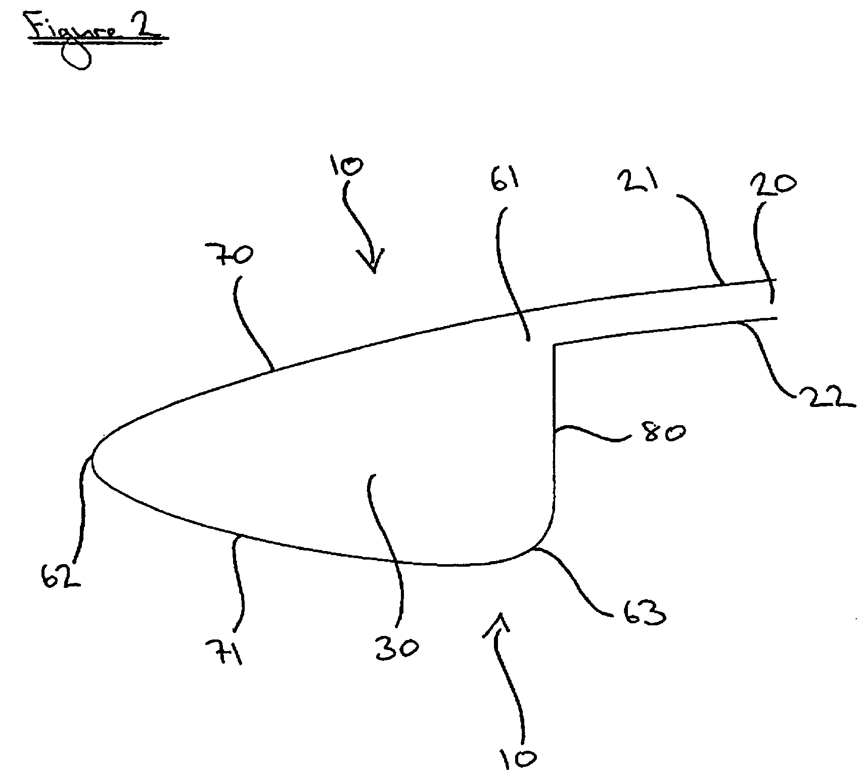
[0073]In a second embodiment, corners and curves 62A, 63A, 70A and 71A of rim 30A of disc 10A are defined by reference to the arcs of circles. Linear dimensions are as for disc 10 (above).

[0074]With the center of the top surface 21A having the (x, y) coordinates in millimeters (0, 0), curves and corners 71A, 63A, 62A and 70A are defined as follows:

[0075]1. Convex curve 71A is an arc of a circle having its center at the coordinates (64.7933, −109.354) and a diameter of 85.5117 mm.

[0076]2. Lower corner 63A is an arc of a circle having its center at the coordinates (85.1931, −12.8839) and a diameter of 5.5208 mm, extending from a point at which it is at zero degrees to the vertical.

[0077]3. Outer corner 62A is as arc of a circle having its center at the coordinates (104.4479, −10.9007) and a diameter of 2.3387 mm.

[0078]4. Convex curve 70A is an arc of a circle having its center at the coordinates (87.4904, 26.8533) and a diameter of 215.5663 mm.

[0079]The four arcs are joined by appropr...

third embodiment

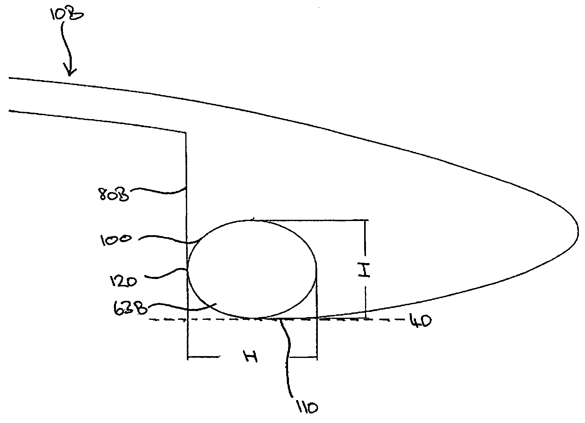
[0080]In a third embodiment, disc 10B has lower corner 63B defined substantially by a section of an ellipse 100 having its center at the coordinates (86.2432, −13.0245), a major axis H having a length of 7.5889 mm and a minor axis I having a length I of 5.7519 mm. Coordinates are relative to the center of the top surface which has the (x, y) coordinates in millimeters (0, 0).

[0081]As is seen in FIG. 5, plane 40 is below ellipse 100 and so only a section of lower corner 63B from the first point 110 (defining lower plane 40) to a second point 120 where lower corner 63B has an angle of zero degrees to the vertical and merges with inside rim 80B is a section of ellipse 100. Overall, the radius of curvature decreases from first point 110 to second point 120.

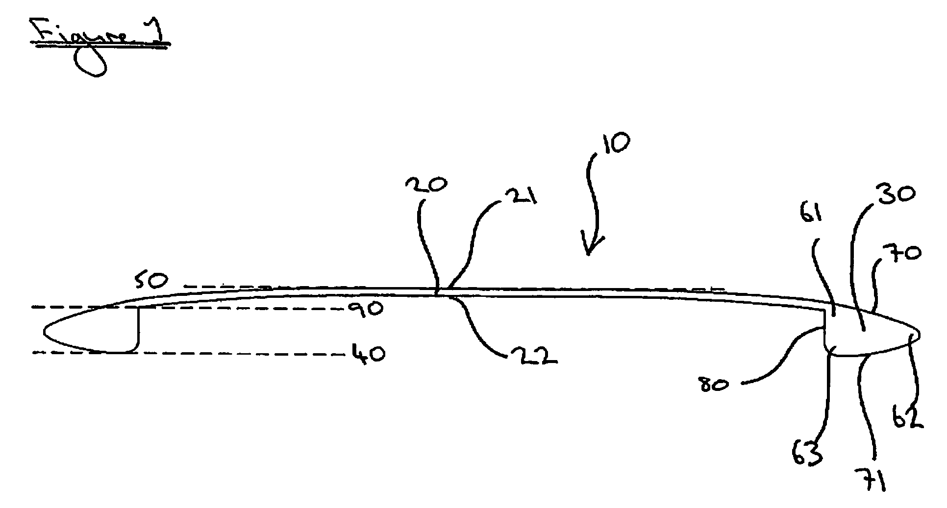
[0082]Each of discs 10, 10A and 10B has enhanced characteristics with regard to the prior art circular planform wings (discs)


PUM


Abstract

A circular planform wing includes a contiguous thin central plate having top and bottom surfaces. An outer annular rim encompasses the central plate. The rim has a lower edge defining a lower plane of the wing, and the central plate has an upper zone defining an upper plane of the wing. The rim has a cross-section with a lower rounded corner forming the lower edge, an outer rounded corner, and an upper corner merging with the central plate, the outer corner being located between the upper plane and the lower plane. The rim cross-section has a convex upper curve joining the outer rounded corner to the upper corner, an inside rim surface joining the lower rounded corner to the upper corner, and a convex lower curve joining the outer rounded corner to the lower rounded corner.

Description

CROSS-REFERENCE TO RELATED APPLICATION[0001]This application claims the benefit of United Kingdom Patent Application No. 0402910.4, filed on Feb. 11, 2004, and U.S. Provisional Patent Application No. 60 / 553,425 filed on Mar. 15, 2004.FIELD OF THE INVENTION[0002]The present invention is concerned with improved circular planform wings, particularly in the form of flying discs.BACKGROUND OF THE INVENTION[0003]Flying toys which are thrown by a user and rotate to effect an aerodynamically optimised flight are widely used and come in a wide variety of forms, from ring structures such as the Aerobie to the Frisbee. Disc Golf is an increasingly popular sport and the flying discs used to play it are regulated by the PDGA (Professional Disc Golf Association) and manufacturers include Ching, Disc Golf Association, Discraft Inc., Disc Golf Stuff, Dynamic Discs, Gateway Disc Sports, Innova-Champion Discs Inc., Lightning Discs, Millennium Golf Discs, Superflight Inc., and Wham-O.[0004]A typical d...

Claims


Application Information

Patent Timeline
Patent Type & Authority Patents(United States)
IPC IPC(8): A63H27/00A63B65/10B64C15/00
CPCA63H33/18
Inventor POTTS, JONATHAN
Owner POTTS JONATHAN
Why Eureka
Try Eureka