Cable-free medical detection and treatment system

a medical detection and treatment system technology, applied in the field of cable-free medical detection and treatment systems, can solve the problems of restricting the freedom of movement of the support staff, affecting the treatment of the physician and the support staff, and affecting so as to improve the overall security of the data transfer, facilitate and less invasive penetration, and transfer sufficiently accurately

Inactive Publication Date: 2007-11-13
BRAINLAB
View PDF29 Cites 183 Cited by
  • Summary
  • Abstract
  • Description
  • Claims
  • Application Information

AI Technical Summary

Benefits of technology

[0006]This object is solved in accordance with the invention by a system for medical detection and treatment comprising a number of treatment and / or detection devices which exchange data with each other within the context of a medical treatment, in particular a surgical or radiotherapeutic and / or radiosurgical operation, wherein said data are exchanged via radio interfaces in and / or on the devices. In other words, a cable-free system is provided with respect to data exchange, which has the major advantage that the cables which were previously required for data exchange are now no longer present in the operating room and also cannot therefore disrupt. Since such systems can in principle easily overcome the distances obtaining in an operation room, there advantageously exists the further possibility of placing all devices which do not necessarily have to be present in the vicinity of the patient bed at a distance from it, such that they do not obstruct. Apparatus for treatment and / or treatment-assisting apparatus can be placed at the most suitable locations, easily and regardless of cable lengths, and can even be hung from the ceiling. Moreover, the handling of hand-held devices or probes is no longer impeded by disruptive data transfer cables.
[0022]For the devices cited above, the possibility of optimally placing or arranging them in the treatment and / or operation room is to be emphasised, and other advantages also arise. For example, instruments for treatment, such as probes for example, can be designed as “intelligent” probes which transmit data concerning their current location or status or the location or status of the detected structures via their interfaces and an operating means (for example a type of mouse click). As far as the use of endoscopes is concerned, the cabling which, when using a miniature transmitter on the endoscopic probe, normally consists of an electric power supply, a light supply, and a line for sending video signals can be reduced by at least said latter video signal line, the possibility existing in principle of scaling down the endoscopic probes and their cable attachments and thus more easily and less invasively penetrating into previously inaccessible target volumes.
[0023]Advantageously, the devices can transfer data concerning their own identification and / or detected medical data and / or data concerning their own position or that of other objects. Transferring data for identifying the devices in particular makes the system very secure as compared to the prior art, since this rules out errors such as arise from defective cable connections. It is possible to carry out radio transmission for a device on a number of varying channels, until a channel is found which allows the data to be transferred sufficiently accurately, which improves the overall security of the data transfer. In this way, the sender and receiver search for a suitable channel until the optimal preconditions for data transfer are created. The coding can be varied, which ensures that the devices are correctly assigned. An identification key for each transmitter ensures straight away that the communication signals are assigned to the correct devices from the start.
[0025]A further major advantage with respect to freedom of movement and reducing the number of cable connections to be provided and / or laid out emerges if the devices are driven by accumulators or batteries, as in accordance with a preferred embodiment of the present invention. Since some of the devices used in such treatment require an electrical power supply, electrical power supply cables are conventionally also necessary to operate them, said cables having the disruptive effect already described. Within the context of the advancement in battery and accumulator technology, it is in principle possible within the framework of the invention to eliminate even these power connections and to provide devices which complete data exchange without cables and use their own power supply. Using this measure, a cable-free operation room can be substantially provided. By omitting cables, disinfection measures can be significantly simplified, and electrical interfaces with delicate plug contacts—which are likewise difficult or impossible to clean—may be omitted. In technical terms, this increases operational safety and simultaneously saves on costs, since costly insulating measures using optical couplers, transmitters etc. as well as ESD protective circuits, for example, may be omitted.

Problems solved by technology

As it often occurs that a multitude of such treatment devices are used, and these devices exchange their data via cable connections in accordance with the prior art, there is more often than not an accumulation of laid cables which disrupt the physicians carrying out the treatment and the support staff, or restrict their freedom of movement.
The cabling means that a few of the devices have to be placed very near to the patient bed, which further restricts freedom of movement.
The situation is made even worse by the fact that said devices essentially require an electric power supply, and for this reason even more cable has to be laid.
Moreover, installing the devices in the operating room is very costly due to the necessity of laying a large number of cables, for which reason technical support staff have to work for a long time in preparation.
Sources of errors arise if connections are inadvertently damaged, or if they corrode, or if other contact problems arise, and individual treatment devices, for example ultrasound probes, can scarcely be packed sterilely, since they hang by the cable connection.

Method used


Image

  • Cable-free medical detection and treatment system
  • Cable-free medical detection and treatment system

Examples


Embodiment Construction

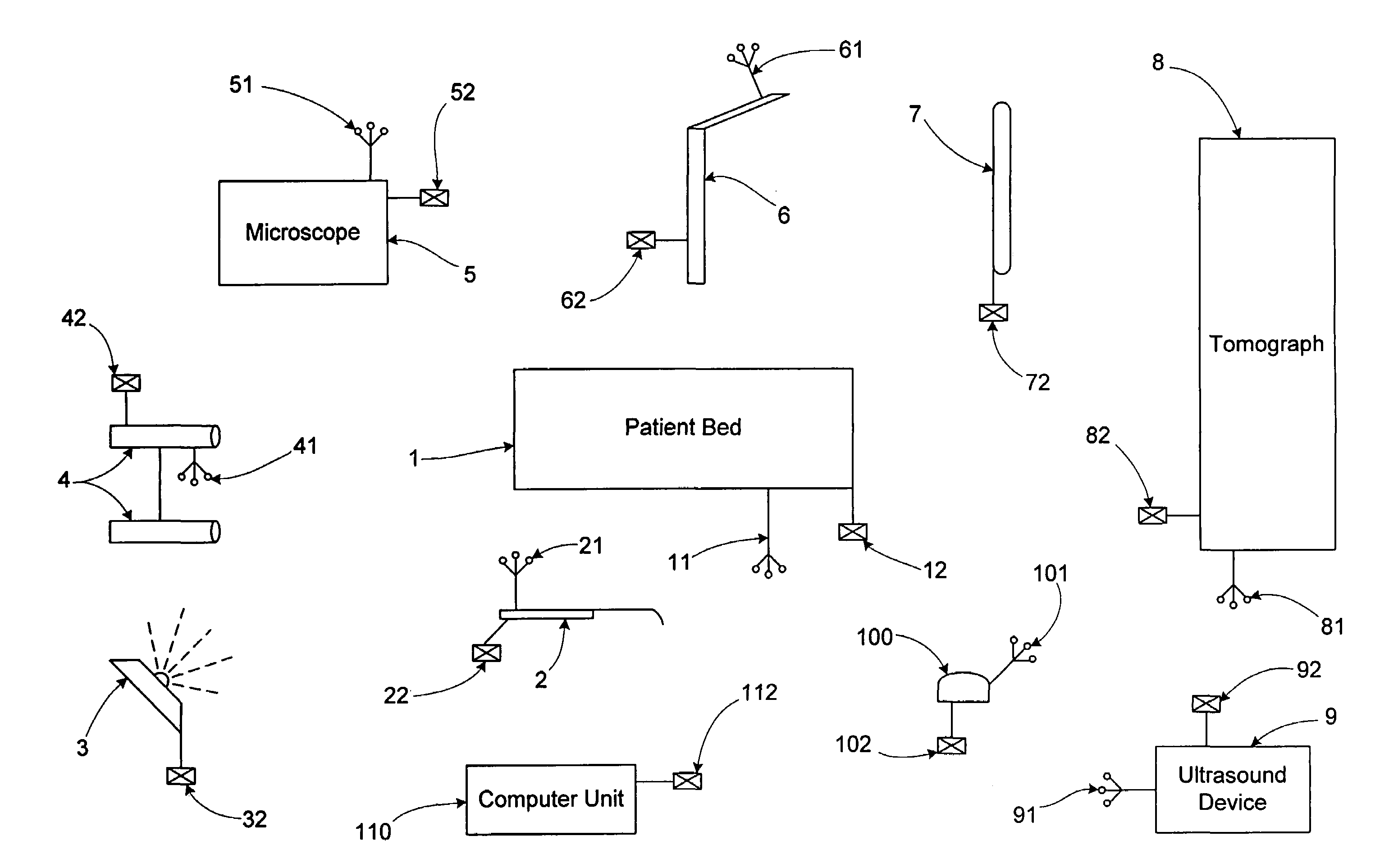
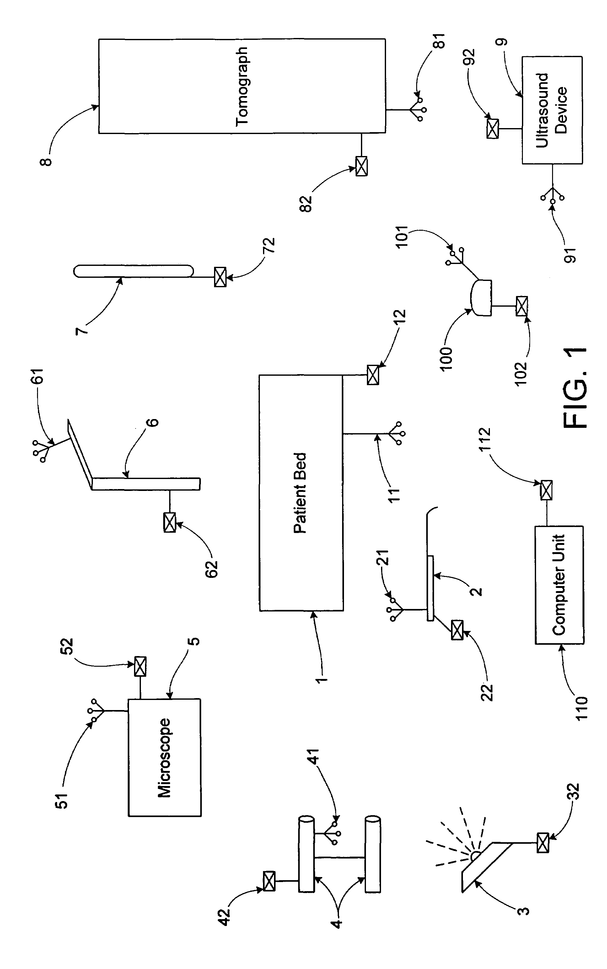
[0029]In the following, the invention will be explained in more detail by way of an example embodiment with the aid of the enclosed drawing. The drawing shows a schematic overview over an operating room comprising treatment and detection devices placed in it. A patient bed 1, a probe 2, which here stands in general for instruments for treatment, such as probes, forceps, scalpels, etc., an infrared light emitter 3, an infrared camera system 4, a surgical microscope 5, a surgical robot 6, a screen 7 as video-support for treatment, an intra-operative nuclear spin tomograph 8 which is arranged portable in such a way that it can be moved over the patient bed 1, an ultrasound device 9 and a corresponding ultrasound probe 100, and a central computer unit 110 are provided in the operating room. Said latter computer unit 110 controls, regulates and processes the processes and information in the system, wherein it is also perfectly possible for individual devices from those cited above themse...


PUM


Abstract

A system for medical detection and treatment comprising a number of treatment and / or detection devices which exchange data with each other within the context of a medical treatment, in particular a surgical or radiotherapeutic and / or radiosurgical operation, wherein the data are exchanged via radio interfaces in and / or on the devices.

Description

[0001]This application is a continuation of U.S. patent application Ser. No. 09 / 999,247 filed on Nov. 1, 2001, now U.S. Pat. No. 6,782,285, which is hereby incorporated herein by reference in its entirety.TECHNICAL FIELD[0002]The present invention relates to a system for medical detection and treatment comprising a number of treatment and / or detection devices which exchange data with each other within the context of a medical treatment, in particular a surgical or radiotherapeutic and / or radiosurgical operation.DESCRIPTION OF RELATED ART[0003]In the course of technical advancement, it is becoming increasingly important, even in the area of medicine, for treatment and / or detection devices to exchange data with each other. In this way, a number of devices already now co-operate under computer guidance by means of data exchange, for example in an operating room, when the operation is assisted by a medical navigation and tracking system. In this respect, position data for example, or da...

Claims


Application Information

Patent Timeline
Patent Type & Authority Patents(United States)
IPC IPC(8): A61B5/00A61B34/20A61B90/00A61N5/10G16H30/20G16H40/63
CPCA61B5/0002A61B19/5244G06F19/3406G06F19/3481Y10S128/903A61B19/5225A61B2019/5255A61B2019/5272A61B2019/5276A61N5/10A61N2005/1074G06F19/321G06F19/327Y10S128/92A61B19/2203A61B2034/2055A61B2034/2072A61B34/20A61B34/30A61B90/37A61B2090/378G16H40/63G16H40/20G16H30/20
Inventor BIRKENBACH, RAINERMULLER, GUNTER
Owner BRAINLAB
Why Eureka
Try Eureka