Microfluidic component and method for sorting particles in a fluid

a microfluidic component and fluid technology, applied in the direction of diaphragms, electrostatic separators, electric/magnetic elements, etc., can solve the problems of time-consuming and complicated analysis by means of such devices, and achieve the effect of reducing the risk of a blockag

Inactive Publication Date: 2007-11-13
AMPHASYS
View PDF10 Cites 34 Cited by
  • Summary
  • Abstract
  • Description
  • Claims
  • Application Information

AI Technical Summary

Benefits of technology

[0017]According to another preferred embodiment, a wide measuring channel is used, which has the advantage that the risk of a blockage is reduced. In this wider measuring channel, the individual particles are deflected onto a specific path on one side of the channel by means of dielectrophoresis and then pass through the measuring field between two electrodes, the reference field being arranged in the area in which no particles move.
[0018]The dimensions of the channel lie in the order of magnitude of the typical particle size to be measured or an order of magnitude above. The electrodes can be arranged in various ways on the walls, in order to provide at least two detection areas in the same channel. The electrodes can be arranged one after another on one side of the channel, circling around the channel, only above, or above and below or laterally. If the electrodes are arranged one after another only on one side of the channel, there is a great influence on the particle position during the measurement. If the position of the particles is to be determined accurately, it is expedient to perform the measurement by means of a differential measurement between an offset upper and lower electrode pair. This has the effect that, depending on the vertical alignment of the particle, the upper or lower electrodes are influenced more or less. In a corresponding way, this can be carried out on the side walls.
[0019]After the individual particles have passed through the measuring channel area, they come into the sorting electrode area having a larger cross section. In order that proper sorting is possible, according to a preferred embodiment, there is upstream of the sorting electrode arrangement an electrode arrangement for aligning the particles, in order to lead the latter onto the narrowest possible path in the fluid flow. This permits exact sorting at high speed, since the corresponding electrodes can have a small electrode length and therefore the path of the sorted particles led out of the particle path is short along the electrodes, and therefore a new selection can be made relatively quickly thereafter.

Problems solved by technology

This makes the analysis by means of such devices complicated and time-consuming.

Method used


Image

  • Microfluidic component and method for sorting particles in a fluid
  • Microfluidic component and method for sorting particles in a fluid
  • Microfluidic component and method for sorting particles in a fluid

Examples


Embodiment Construction

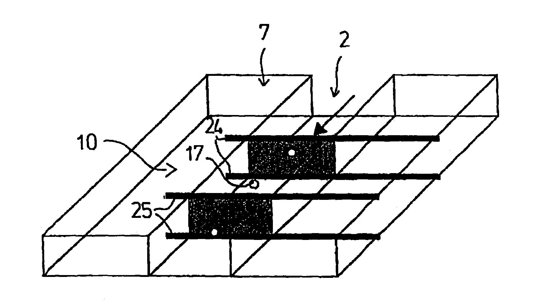
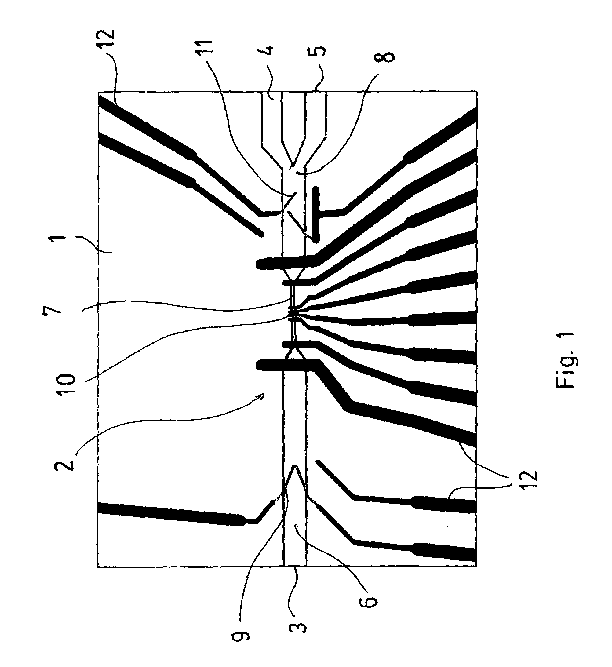
[0040]The schematic view in FIG. 1 shows a plan view of a microfluidic component 1, which shows an elongate channel 2 which on the left-hand side has an inlet opening 3 and on the right-hand side has two outlet openings 4 and 5. Of course, a corresponding component 1, if necessary, can also have a plurality of outlet openings or else inlet openings. The inlet openings can be connected to appropriately suitable devices for feeding a fluid, which can be liquid or possibly also gaseous. Accordingly, the outlet openings 4 and 5 are also connected to appropriate devices to accommodate the particles sorted out. In the following text, in connection with the exemplary embodiments, a liquid will be assumed, which transports various types of particle, for example biological cells.

[0041]The channel 2 is divided into a preparation area 6, a measuring channel area 7 and a sorting area 8. The cross sections of the individual areas are different, in particular the measuring channel area 7 being su...


PUM

PropertyMeasurementUnit
frequencyaaaaaaaaaa
peak-to-peak voltagesaaaaaaaaaa
sizeaaaaaaaaaa

Abstract

Microtechnologically prepared component as a flow cytometer. The component contains a preparation area to specifically influence and separate the particles, preferably by dielectrophoresis, a measuring channel area for characterizing the particles, and a sorting area for sorting the particles identified in the measuring channel area by dielectrophoresis. The sorting includes switching elements which permit active guidance of the particles into two or more subchannels corresponding to the criteria which have been registered in the measuring channel area. With a component configured in this way for the use of a flow cytometer, quick and precise sorting of particles, in particular biological cells in a suspension, can be implemented.

Description

BACKGROUND OF THE INVENTION[0001]The present invention relates to a microfluidic component comprising a substrate having a channel for leading individual particles through for sorting particles in a fluid flow, in particular a liquid flow, and also a method for sorting particles.[0002]The manipulation of suspended particles is generally known and is described, for example, by G. Fuhr et al in “Naturwissenschaften” [Natural sciences] volume 81, 1994, page 528 ff. Here, the suspended particles can be any desired particles or else biological cells. In the following text, therefore, in general only particles will be mentioned. The microsystems form in particular channel structures through which a suspension liquid with the particles to be manipulated flow. In the channel structures, microelectrodes are fitted to the channel walls and have high-frequency electric fields applied to them. Under the action of the high-frequency electric fields between two electrodes, polarization forces are...

Claims


Application Information

Patent Timeline
Patent Type & Authority Patents(United States)
IPC IPC(8): G01N27/02G01F1/64G01N15/14B01D57/02B01L3/00B03C5/00B03C5/02C12M1/00G01N15/10G01N27/00G01N27/447G01N37/00
CPCB01L3/502761B03C5/026G01N15/1031G01N15/1056B01L3/502784B01L2200/0636B01L2200/0647G01N2015/1006G01N27/02B01L2400/0415
Inventor GAWAD, SHADYWUTHRICH, MARTINRENAUD, PHILIPPE
Owner AMPHASYS
Why Eureka
Try Eureka