Object identification

a technology of object identification and object, applied in the field of object identification, can solve the problems of significant loss of image information, loss of information relating to structure close to the edges, and model prone to function incorrectly

Inactive Publication Date: 2007-11-13
UNIV OF MANCHESTER
View PDF3 Cites 44 Cited by
  • Summary
  • Abstract
  • Description
  • Claims
  • Application Information

AI Technical Summary

Benefits of technology

[0009]It is an object of the present invention to provide an appearance model which overcomes or mitigates at least one of the above disadvantages.

Problems solved by technology

A disadvantage of statistical appearance models that are based upon intensity variation information is that these models are prone to function incorrectly in the presence of changing lighting effects.
For example, a face illuminated from an angle different to the illumination which was used when generating the model may cause an error.
The first disadvantage is that the resulting images are binary images, each edge being represented by ‘on’ values, with the result that a significant amount of information relating to the image is lost.
In particular, information relating to structure close to the edges is lost.
The second disadvantage of the method is that the filter parameters remain the same for every area of each image, and remain the same for every image.
Although it is possible to adjust the filter parameters, tile method does not provide any measurement upon which to base any adjustment.

Method used


Image

  • Object identification

Examples


first embodiment

[0035]the invention is based upon the Active Shape Model (ASM) [4 ], which is described in detail in Appendix 1. The known prior art ASM comprises a statistical model of the intensity of the image at each model point.

[0036]The first embodiment of the invention, instead of simply using intensity measurements, represents the image structure as a gradient, which is specified as a magnitude and an orientation. For any given pixel, the orientation of the gradient indicates the direction of greatest intensity change when moving from that pixel to an adjacent pixel. Where an edge of a feature passes through or adjacent the pixel, the direction of the gradient will be transverse to the edge. The magnitude of the gradient provides a measure of belief in the accuracy of the measurement (in other words a measure of belief that an edge is present). Essentially the measure is strong when on a well defined edge, since the orientation of the gradient is well defined, but is weak or zero in essenti...

second embodiment

[0069]During both model building and image search, the image of interest is sampled over each region of interest, the sample values being placed in a vector representing, the image structure in the region. In prior art AAM's this was commonly simply a case of taking the intensity values at each pixel in the region and placing them in the vector. the invention uses the following approach to represent each region within a vector:

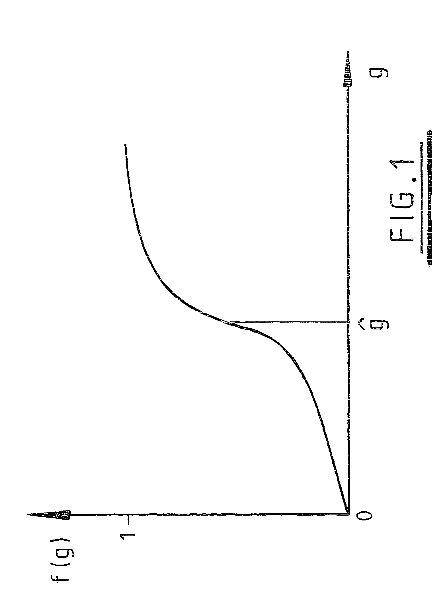
[0070]For a 2D image, the following steps are performed at each pixel:[0071]1. Estimate the local gradients at a point x in x and v. The gradient is determined by first applying an edge filter in x (essentially convolving with a (−101) filter), then in y. This provides gradient values gx, gy for each point x. The direction in which the gradient is a maximum is given by the vector (gx, gy)[0072]2. Compute the magnitude of the gradient, g=√{square root over (gx2+gy2)}[0073]3. Apply a non-linear function, ƒ(g, x) to obtain a representation of gradient direction a...


PUM


Abstract

A method of object identification comprising, for an image in which an object is to be identified, determining for each of a set of location in the direction in which the gradient of intensity change to an adjacent location is greatest together with the magnitude of that gradient, modifying the gradient magnitude using a nonlinear function, the modified gradient and the associated direction for the set of location providing a vector representative of the image, and comparing the vector with a previously generated statistical model which provides identification of the object.

Description

[0001]This application is the U.S. national phase of international application PCT / GB02 / 02228, filed May 24, 2002, which designate the U.S.BACKGROUND[0002]1. Technical Field[0003]Statistical models of appearance are widely used in computer vision and have many applications, including interpreting medical images and interpreting images containing faces.[0004]2. Related Art[0005]Conventionally, a statistical model is built which represents intensity (greyscale or colour) variation across an image or part of an image. In the case of a facial appearance model, images of many faces are used to generate the model, these images being known as training images. The intensity variation that is likely to be seen in any given face will tend to include similar patterns, and the statistical model represents these patterns. Once the statistical model has been built it may be used to determine whether a new image includes a face, by determining whether the new image contains the facial intensity pa...

Claims


Application Information

Patent Timeline
Patent Type & Authority Patents(United States)
IPC IPC(8): G06K9/48G06K9/00G06T7/00G06K9/62G06K9/64G06T7/60
CPCG06K9/00275G06K9/6232G06K9/621G06V40/169G06V10/7557G06F18/213
Inventor COOTES, TIMOTHY F.TAYLOR, CHRISTOPHER J.
Owner UNIV OF MANCHESTER
Why Eureka
Try Eureka