
Tree processing equipment with two position pivot point for actuator ends

a technology of actuator end and processing equipment, which is applied in the direction of woodworking apparatus, manufacturing tools, agriculture, etc., can solve the problems of difficult, if not impossible processing of trees, and the equipment of the art tree processing equipment is not designed to operate at extreme angles of inclination, so as to increase the rotational angle of the processing head, and increase the angular rotation

Active Publication Date: 2007-11-20
BARKO SPECIALTY EQUIP
View PDF7 Cites 18 Cited by
  • Summary
  • Abstract
  • Description
  • Claims
  • Application Information

AI Technical Summary

Benefits of technology

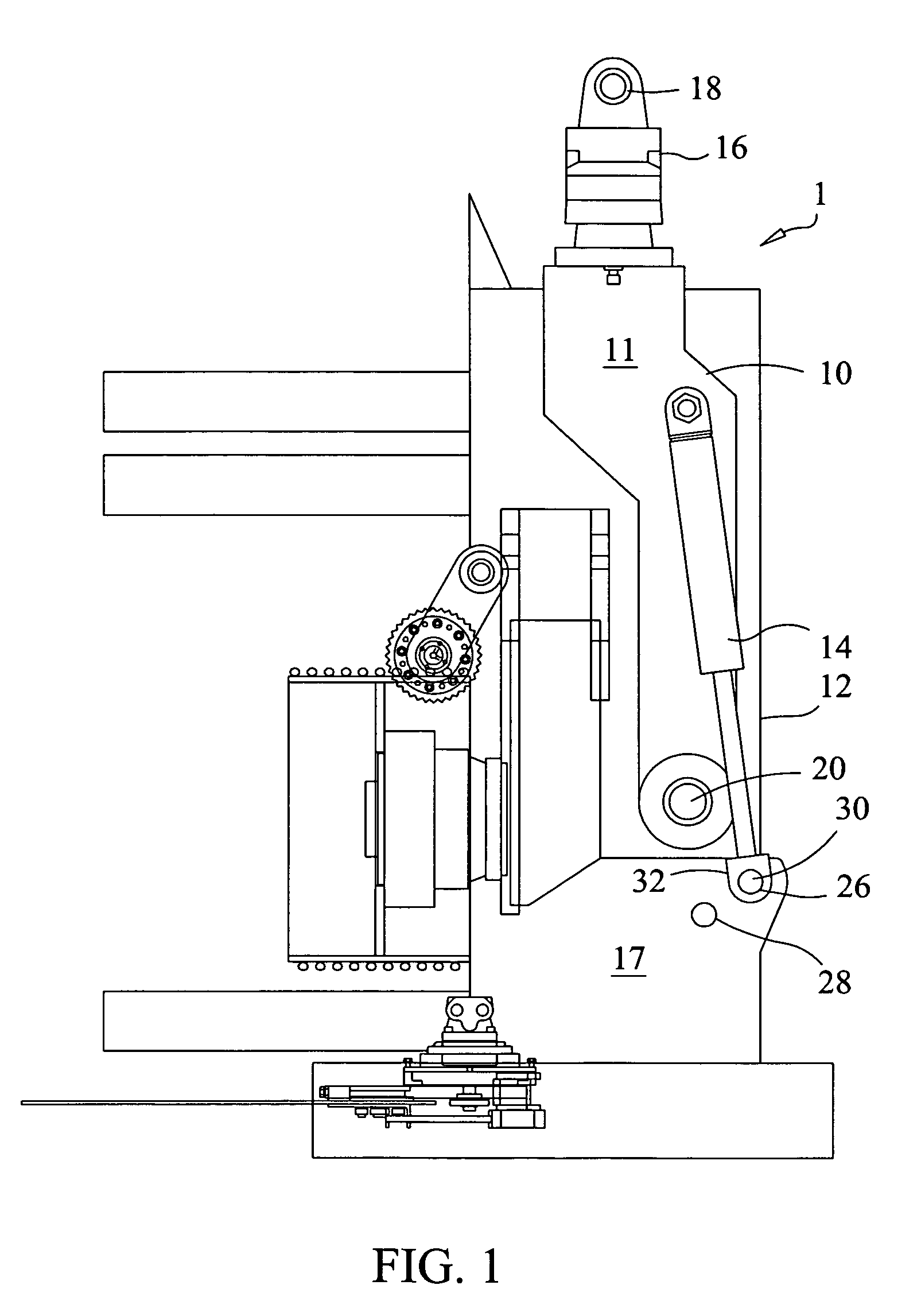
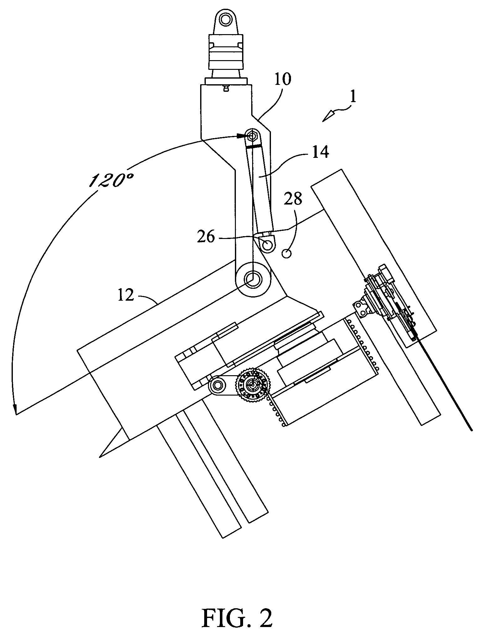
[0007]A first pivot hole and a second pivot hole are formed through the processing head. A pivot pin is inserted through an actuation end of the actuator and the first pivot hole for harvesting and processing in normal terrains or harvesting in mountainous terrains. The pivot pin is inserted through the actuation end of the actuator and the second pivot hole for increasing angular rotation of the processing head relative to the retention bracket for processing trees in mountainous terrains.
[0008]In a second embodiment of the improved tree processor, the first and second pivot holes are formed through the retention bracket and not the processing head. The pivot pin is removable from the actuation end of the actuator and the first or second pivot holes. The second pivot hole increases the angular rotation of the processing head relative to the retention bracket for processing trees in mountainous terrains.
[0009]Accordingly, it is an object of the present invention to provide an improved tree processor, which allows the rotational angle of the processing head to be increased relative to a retention bracket for mountainous terrains.

Problems solved by technology

State of the art tree processing equipment is not designed to operate at extreme angles of inclination.
As a result processing trees becomes difficult, if not impossible in certain geographic areas.
However, the two positions of the coupler relative to the processing head do not increase a rotational angle of the processing head relative to the coupler.

Method used


Image

  • Tree processing equipment with two position pivot point for actuator ends
  • Tree processing equipment with two position pivot point for actuator ends
  • Tree processing equipment with two position pivot point for actuator ends

Examples


Embodiment Construction

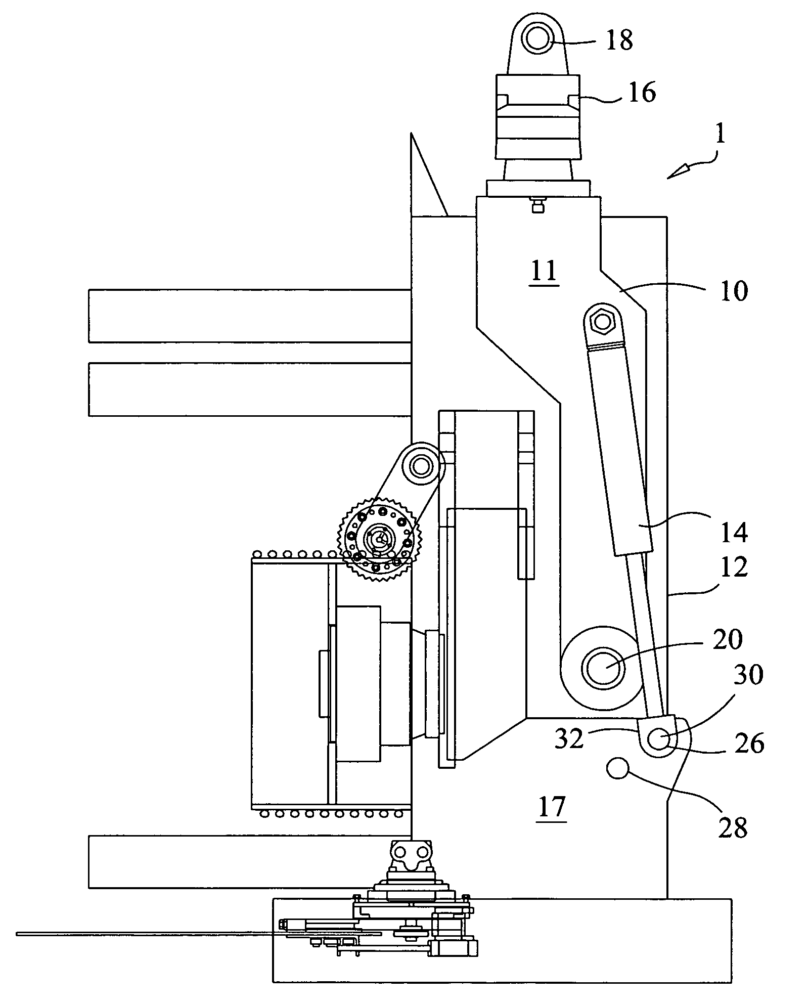
[0024]With reference now to the drawings, and particularly to FIG. 1, there is shown a side view of an improved tree processor 1. With reference to FIGS. 2-7, the improved tree processor 1 includes a retention bracket 10, a processing head 12 and an actuator 14. The retention bracket 10 includes a pair of bracket support plates 11. The processing head 12 includes a pair of pivot plates 15 and at least one actuation plate 17. Processing heads are well known in the art and need not be explained in detail. A rotator 16 is attached to a top of the retention bracket 10. The rotator 16 is pivotally retained on an end of a forestry equipment boom (not shown) by inserting a pin through the end of the forestry equipment boom and a retention bore 18. The rotator 16 allows the retention bracket 10 to be rotated relative to the forestry equipment boom.

[0025]A bottom of the pair of retention bracket support plates 11 are pivotally attached to the pair of pivot plates 15 of the processing head 12...


PUM


Abstract

Tree processing equipment with two position pivot point for actuator ends includes a retention bracket, a processing head and at least one actuator. A bottom of the retention bracket is pivotally attached to the processing head. One end of the actuator is pivotally attached to the retention bracket and an actuation end is pivotally attached to the processing head. A first pivot hole and a second pivot hole are formed through the processing head or the retention bracket. A pivot pin is inserted through an actuator end and the first pivot hole for harvesting and processing in normal terrains. The pivot pin is inserted through one of the actuator ends and the second pivot hole for processing trees in mountainous terrains.

Description

BACKGROUND OF THE INVENTION[0001]1. Field of the Invention[0002]The present invention relates generally to tree processing equipment and more specifically to tree processing equipment with two position pivot point for actuator ends.[0003]2. Discussion of the Prior Art[0004]Tree processing heads have a limited rotation angle relative to a retention bracket. In mountainous terrains, the tree processing equipment is forced to operate at extreme angles of inclination. State of the art tree processing equipment is not designed to operate at extreme angles of inclination. As a result processing trees becomes difficult, if not impossible in certain geographic areas. U.S. Pat. No. 6,962,178 to Duval discloses a tree processor. The Duval patent includes a coupling and processing head. Two pairs of apertures are formed in the processing head. The coupler is mounted to either one of the two pairs of apertures with a shaft. One end of an actuator is mounted to the coupler and the other end is m...

Claims


Application Information

Patent Timeline
IPC IPC(8): A01G23/08
CPCA01G23/091
Inventor RIHA, GARY D.DUBEY, DONALD A.
Owner BARKO SPECIALTY EQUIP
Learn More