Shipping container

a container and end cap technology, applied in the field of shipping containers, can solve the problems of damage to the end cap, plastic plug use, paper tube and/or end cap damage, etc., and achieve the effect of convenient rotation and removal of the end cap, convenient reuse and easy removal by hand

Active Publication Date: 2007-11-20
ERDIE END CAPS LLC
View PDF26 Cites 19 Cited by
  • Summary
  • Abstract
  • Description
  • Claims
  • Application Information

AI Technical Summary

Benefits of technology

[0010]Preferably, each projection is formed on a deflectable tab portion of the circular sidewall. Each projection preferably comprises a top edge portion that is arranged to contact against a top peripheral portion of the mounting opening, which prevents withdrawal of the end cap from the tube. Each projection also preferably comprises a bottom ramp portion that is arranged opposite the top edge portion for promoting deflection of the deflectable tab when the end cap is received by the open end of the tube, and a side ramp portion that is arranged between the top edge portion and the bottom ramp portion to promote deflection of the deflectable tab when the end cap is rotated relative to the tube at a time when the projection extends into the mounting opening. The end cap preferably further comprises an end wall that extends between the circular sidewall. The end wall can further comprise a handle portion for facilitating rotation of the end cap relative to the tube.
[0012]The end cap can be selectively released from the tube simply by rotating the end cap relative to the tube. The side ramp portion of the projection causes the deflectable tab to be deflected inwardly until the top edge portion of the projection is no longer aligned with and thus cannot contact the top peripheral portion of the mounting opening. After rotation, the end cap can simply be withdrawn from the tube by pulling the end cap from the tube. The handle portion of the end wall facilitates both rotation and removal of the end cap from the tube.
[0013]The shipping container according to the invention is light in weight and very strong. The end cap can be releasably secured to the tube to close off the open end without the need for special tools. Furthermore, the end cap is very difficult to accidentally or unintentionally dislodge from the tube. However, it can be easily removed by hand and reused. No fasteners or adhesives of any type need be used to keep the end cap secured to the tube.

Problems solved by technology

There are some drawbacks with the use of plastic plugs, however.
The plugs can “pop” out when the paper tube is squeezed or when the contents of the container shift during transit and strike the interior side of the bottom wall causing it to become dislodged from the paper tube.
Both of these solutions are disadvantageous because they require additional time consuming steps or procedures.
Moreover, use of adhesive or staples can damage the tube and / or end cap, which prevents reuse.

Method used


Image

  • Shipping container
  • Shipping container
  • Shipping container

Examples


first embodiment

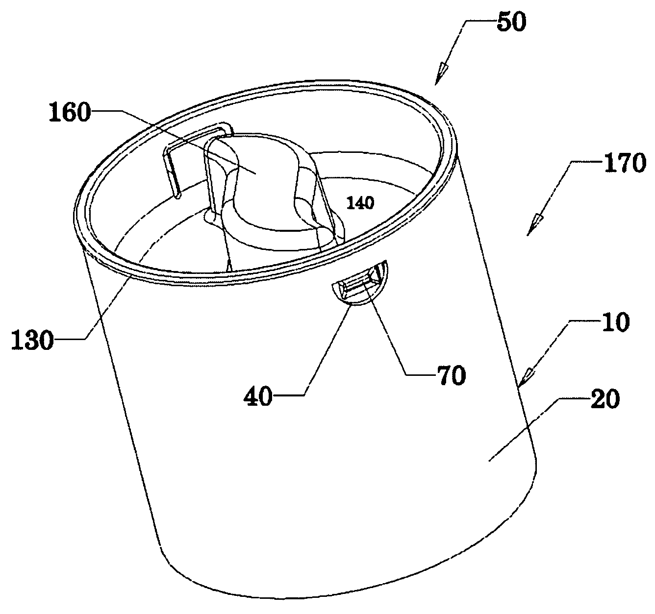
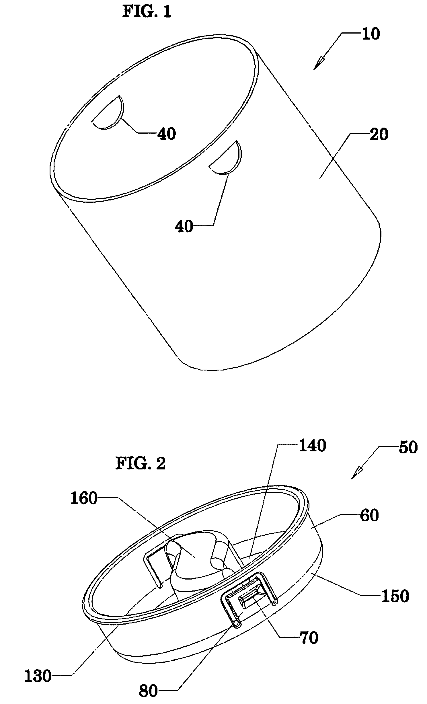
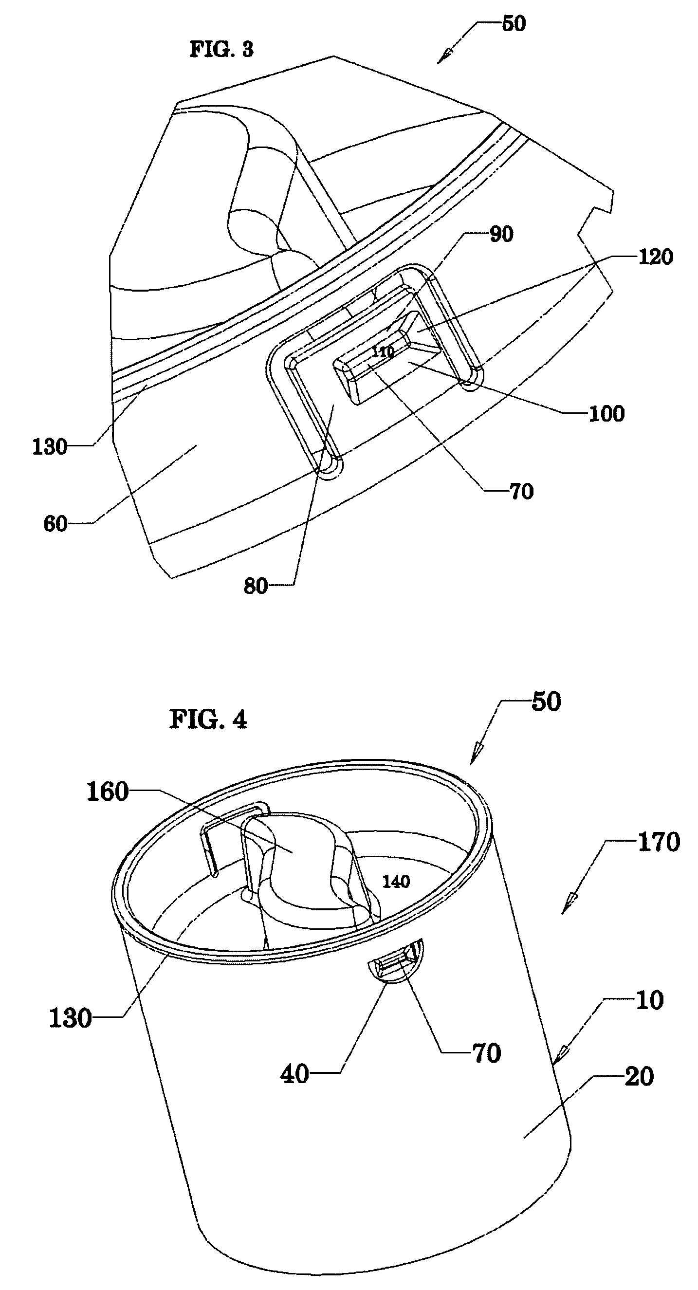
[0031]FIG. 4 shows a perspective view of an exemplary shipping container 170 that can be formed by joining a tube 10 and an end cap 50 according to the invention together. As shown in FIG. 4, the end cap 50 closes or seals off the open end 30 of the tube 10. The end cap 50 is received within the open end 30 of the tube 10 such that the cylindrical body 20 radially surrounds the circular sidewall 60. At least one projection 70 extends away from the circular sidewall 60 and into a corresponding mounting opening 40 so as to releasably secure the end cap 50 to the tube 10.

[0032]With reference to FIG. 5, which shows a detailed perspective view of a portion of the shipping container 170 shown in FIG. 4, the top edge portion 90 of the projection 70 is arranged to contact against a top peripheral portion 180 of the mounting opening 40 to thereby prevent withdrawal of the end cap 50 from the tube 10. Rotation of the end cap 50 relative to the tube 10, however, causes the side ramp portion 12...

second embodiment

[0034]FIG. 7 shows a perspective view of an exemplary shipping container 171 according to the invention. The shipping container 171 includes an end cap 51 having a circular sidewall 61 that radially surrounds a cylindrical body 20 of a tube 10 adjacent to an open end. Projections 71 extending inwardly away from the circular sidewall 61 extend into the mounting openings 40 formed in the cylindrical body 20 of the tube adjacent to the open end and thereby prevent the unintentional removal of the end cap 51 from the tube 10.

[0035]No handle portion need be provided on the end cap 51. A user simply grips the circular sidewall 61 and twists or rotates it relative to the tube 10. The side ramp (not shown) contacts the side peripheral portion of the mounting opening and thereby deflects the deflectable tab portion of the end cap outwardly until the top edge portion of the projection 71 is not longer aligned with and extending into the mounting opening or in contact with the top peripheral p...


PUM


Abstract

The present invention provides a shipping container, a paper tube, an end cap and a method. The shipping container includes a tube and an end cap. The tube has a cylindrical body and an open end. The cylindrical body has a mounting opening formed therein adjacent to the open end. The end cap includes a circular sidewall that is adapted to be received by the open end of the tube such that either the circular sidewall is surrounded by the cylindrical body or the cylindrical body is radially surrounded by the circular sidewall. The circular sidewall includes a projection that extends away from the circular sidewall and into the mounting opening so as to releasably secure the end cap to the tube.

Description

BACKGROUND OF THE INVENTION[0001]1. Field of Invention[0002]The present invention relates to shipping containers and, more particularly, to shipping containers comprising a tube and an end cap that is releasably secured to the tube.[0003]2. Description of Related Art[0004]Paper tubes are conventionally formed by adhesively bonding two or more continuous strips of paper to each other in overlapping layers around a cylindrical mandrel and then cutting the paper cylinder or tube thus formed to desired length. The open ends of the paper tube can then be closed using end closures to form a shipping container that is both light in weight and strong. Shipping containers of this type are often used to ship large-format papers or photos, which can be rolled and stored inside the tube. Shipping containers of this type are provide more protection to contents stored within the tube and are easier to handle than oversized envelopes.[0005]A variety of end closures are known in the art for closing...

Claims


Application Information

Patent Timeline
Patent Type & Authority Patents(United States)
IPC IPC(8): B65D43/04B65D43/18B65D3/10B65D43/02B65D59/02B65D59/06
CPCB65D43/021B65D59/02B65D59/06B65D43/0212B65D2543/00851B65D2543/00092B65D2543/00296B65D2543/00509B65D2543/00527B65D2543/00537B65D2543/00546B65D2543/00574B65D2543/00666B65D2543/00694B65D2543/0074B65D2543/00805
Inventor ERDIE, JASON S.
Owner ERDIE END CAPS LLC
Why Eureka
Try Eureka