Apparatus and methods for minimizing solid particle erosion in steam turbines

a technology of steam turbines and solid particles, applied in mechanical apparatus, combination engines, machines/engines, etc., can solve the problems of reducing steam turbine performance and mechanical reliability, affecting the efficiency of steam turbines, and the opportunity to inflict considerable damage to steam paths

Active Publication Date: 2007-11-20
GE INFRASTRUCTURE TECH INT LLC
View PDF22 Cites 22 Cited by
  • Summary
  • Abstract
  • Description
  • Claims
  • Application Information

AI Technical Summary

Benefits of technology

[0005]In a further preferred embodiment of the present invention there is provided a method of minimizing solid particle erosion in a steam turbine stage comprising the step of diverting a portion of the steam in a steam flow path through a hole in an appendage of an outer ring overlying bucket tips of the turbine stage and bypassing the buckets of the turbine stage.

Problems solved by technology

As they pass through the steam turbine, the particles cause damage to both the stationary and rotating parts of the turbine that degrade steam turbine performance and mechanical reliability.
However, since the particles are transported by the main steam flow through the steam turbine steam path, they have the opportunity to inflict considerable damage to the steam path before they are deposited or expelled from the main steam flow.
This damage can include erosion of the rotating and stationary buckets and partitions respectively, erosion of the rotating tip covers or tenons, erosion of tip sealing devices such as spill strips and erosion of stationary structures over the tips of the rotating buckets.
While many of these and other efforts to minimize or eliminate solid particle erosion have been tried in the past, solid particle erosion in steam turbines remains a continuing problem for the various parts along the steam path.

Method used


Image

  • Apparatus and methods for minimizing solid particle erosion in steam turbines
  • Apparatus and methods for minimizing solid particle erosion in steam turbines
  • Apparatus and methods for minimizing solid particle erosion in steam turbines

Examples


Embodiment Construction

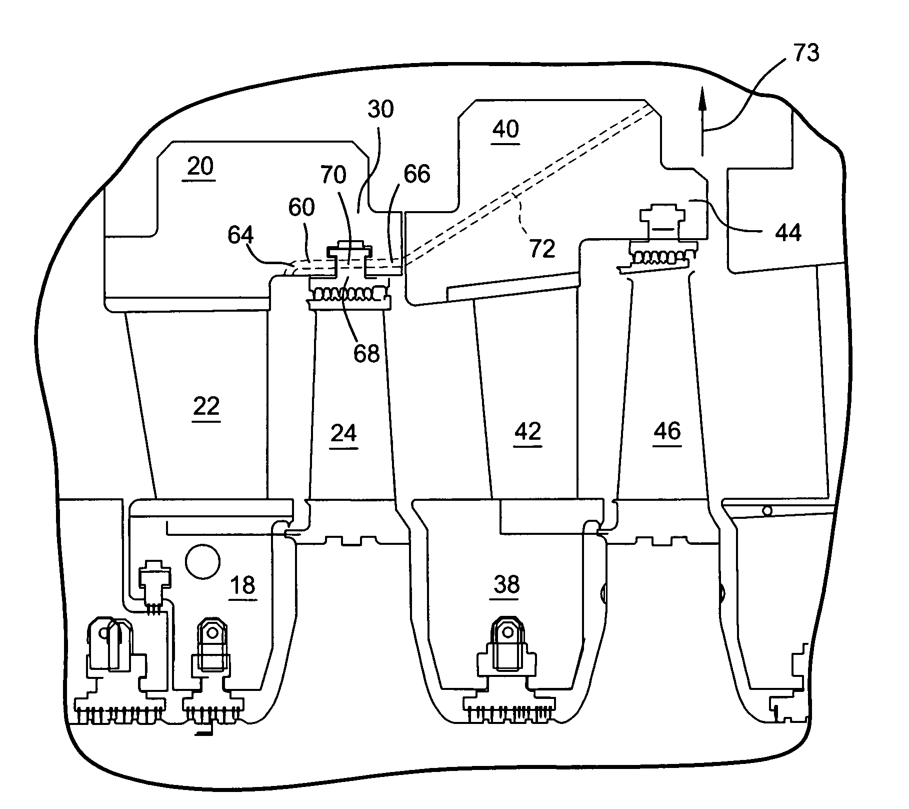
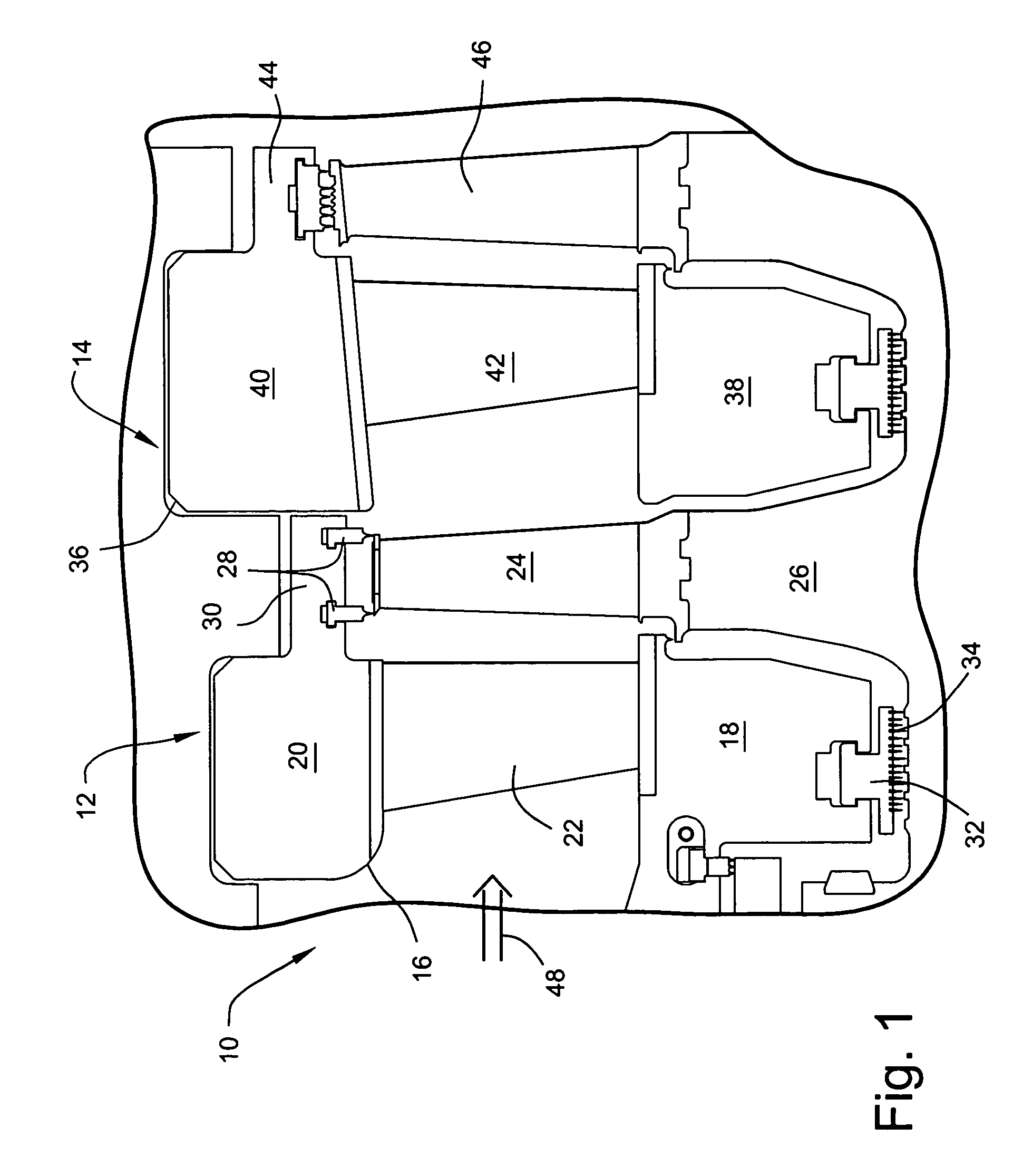
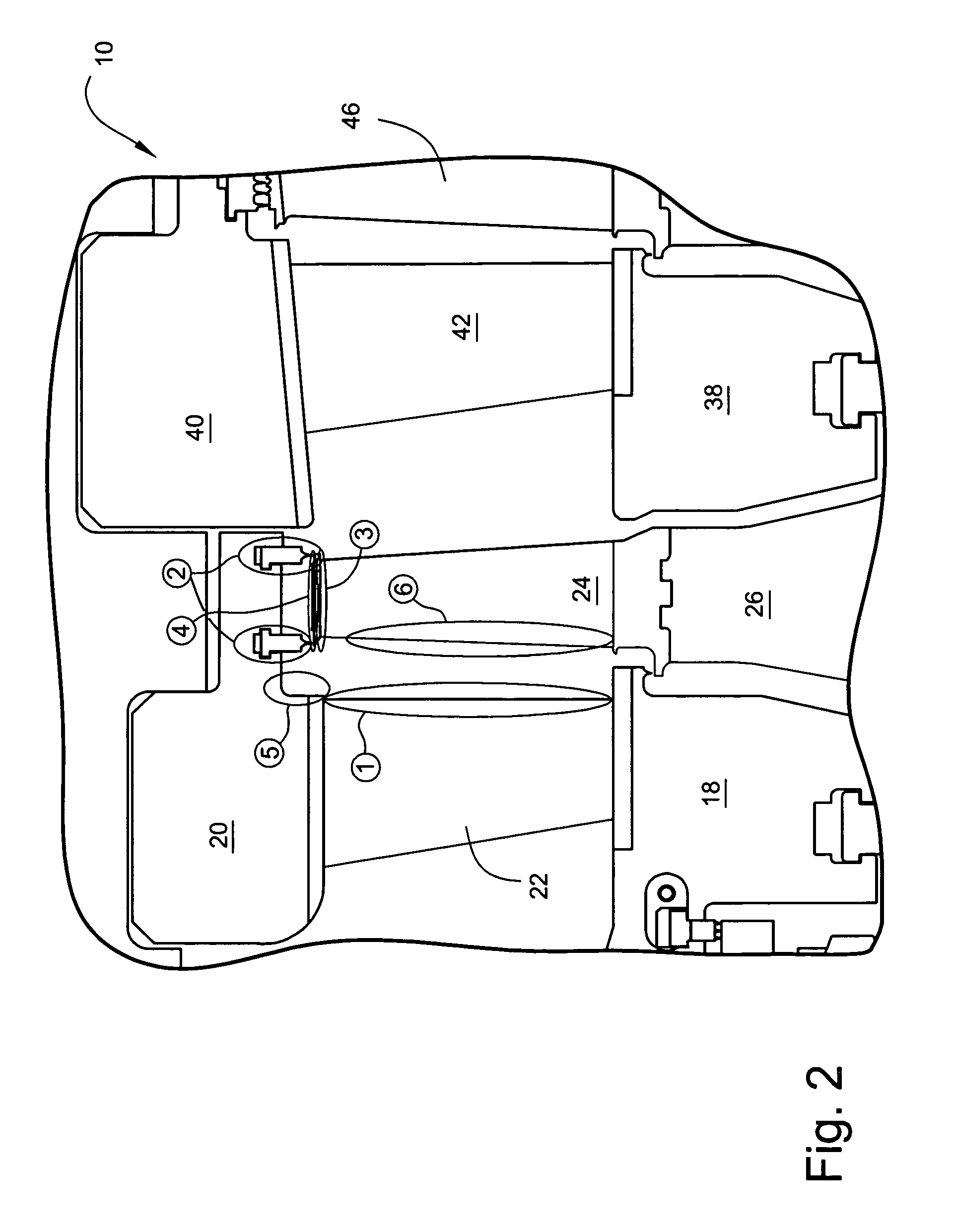
[0012]Referring now to FIG. 1, there is illustrated typical steam turbine stages of a steam turbine generally designated 10. Two stages of the steam turbine 10 are illustrated, for example, a first stage generally designated 12 and a second stage generally designated 14. The first stage 12 includes a diaphragm 16 having an inner web 18, an outer ring 20, and a plurality of circumferentially spaced stator vanes or partitions 22 therebetween. The first stage also includes buckets 24 secured to a rotor 26. The tips of the buckets 24 rotate past sealing devices 28 formed on an axially extending appendage 30 of the outer ring 20. The inner web 18 of the first stage diaphragm includes sealing segments 32, in this instance, mounting labyrinth seal teeth 34 for sealing about the rotor 26. The second stage 14 is similar and includes a diaphragm 36, an inner web 38, an outer ring 40, partitions 42 circumferentially spaced one from the other and disposed between the inner web and outer ring, t...


PUM


Abstract

Solid particle erosion in a steam turbine is minimized by diverting through holes in appendages of outer rings of the diaphragms, a portion of the steam from the steam flow path thereby bypassing downstream rotating components. The hole through the first stage appendage lies in communication with a passage through a downstream outer ring of a following stage such that the diverted solid particle containing steam may be extracted from the steam flow path and passed to the feed water heater of the turbine. The hole in the second stage appendage diverts steam from between the first and second stages and about the second stage. Solid particle erosion in various regions, i.e., the trailing edge of the stator vanes, along the surfaces of the buckets and in the regions of the cover and its connection with the buckets as well as the sealing devices are thereby minimized.

Description

[0001]The present invention relates to apparatus and methods for minimizing solid particle erosion in steam turbine components and particularly relates to apparatus and methods for removing solid particles from the steam flow path to minimize damage to the turbine components.BACKGROUND OF THE INVENTION[0002]Solid particle erosion of the components of a steam turbine occurs due to carryover of particles from the steam boiler and piping upstream of the turbine. The solid particles become entrained in the steam flow path. As they pass through the steam turbine, the particles cause damage to both the stationary and rotating parts of the turbine that degrade steam turbine performance and mechanical reliability. The solid particles may be deposited throughout the steam path or may exit the steam path into steam extractions that feed the feed water heaters of the cycle. However, since the particles are transported by the main steam flow through the steam turbine steam path, they have the o...

Claims


Application Information

Patent Timeline
Patent Type & Authority Patents(United States)
IPC IPC(8): F01D25/26
CPCF01D11/001F01D11/02F01D11/08F05D2260/607F05D2220/31
Inventor MONTGOMERY, MICHAEL EARL
Owner GE INFRASTRUCTURE TECH INT LLC
Why Eureka
Try Eureka