
Particle damage protection for high power co2 slab laser mirrors

Active Publication Date: 2010-07-08
COHERENT INC
View PDF6 Cites 1 Cited by
  • Summary
  • Abstract
  • Description
  • Claims
  • Application Information

AI Technical Summary

Benefits of technology

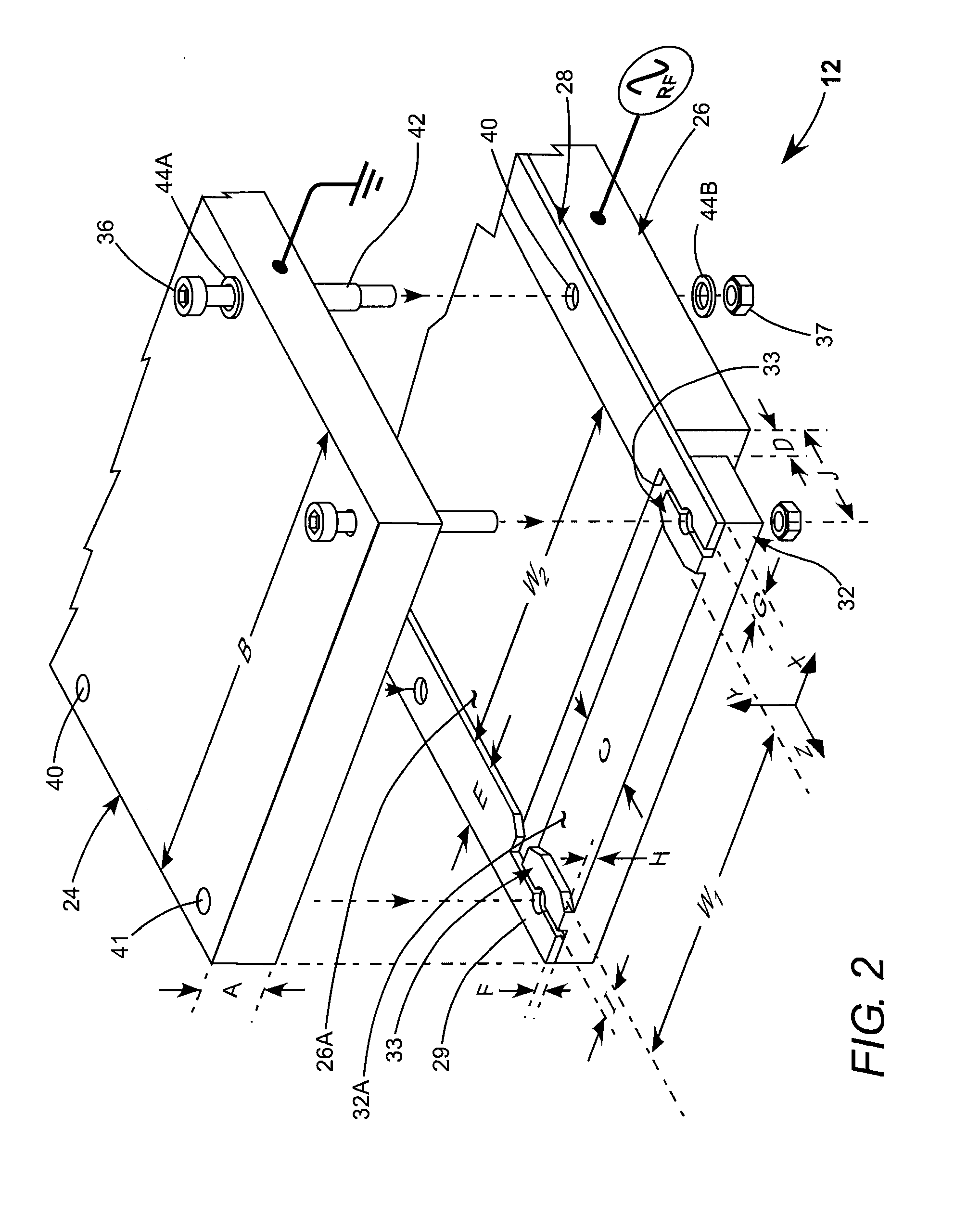
[0011]In one aspect a RF power driven gas discharge laser comprises first and second elongated planar discharge-electrodes arranged vertically spaced apart and parallel to each other. The electrodes are electrically insulated from each other with the first electrode functioning as a live electrode and arranged to receive the RF power from a source thereof and the second electrode functioning as a ground electrode. The discharge electrodes are spaced apart by first and second electrically insulating spacer strips having first and second opposite ends and arranged along opposite edges of the electrodes with inside edges thereof laterally spaced-apart by a first distance. The spacer strips have a height which determines the vertical spacing of the live and ground electrodes. First and second mirrors form a laser resonator extending longitudinally through the space between the discharge electrodes, such that when a discharge is created in a lasing gas between the discharge electrodes when the first electrode receives the RF power, laser radiation circulates in the laser resonator. A planar auxiliary electrode is located at each end of the first electrode, longitudinally spaced apart from the first electrode, vertically spaced apart from the ground electrode and electrically connected to the second electrode. The auxiliary electrode has two raised portions thereon having a height about equal to the height of the spacer strips and laterally spaced apart by a second distance less than the first distance. The raised portions of the auxiliary electrodes minimize erosion of the insulating spacer strips by the laser radiation.

Problems solved by technology

All three possibilities can damage the mirrors, thereby causing reduced laser performance from the standpoint of output power, beam quality, and lifetime.
A problem with such spacers is that if laser power is sufficiently high, for example, about 3000 Watts (W) peak and 1000 Hz pulse repetition frequency (PRF) the ends of the ceramic spacers can be ablated by stray laser radiation, generating ceramic particles which can be deposited on the mirrors.
Such deposits cause sites for further laser radiation damage.
The methods described in the '689 patent successfully address the problem of damage to the laser mirrors by the oxidizing species but do not address the problem of damage from particulates ablated from the ceramic spacers, as laser power was not high enough for such ablation to occur.

Method used


Image

  • Particle damage protection for high power co2 slab laser mirrors
  • Particle damage protection for high power co2 slab laser mirrors
  • Particle damage protection for high power co2 slab laser mirrors

Examples


Embodiment Construction

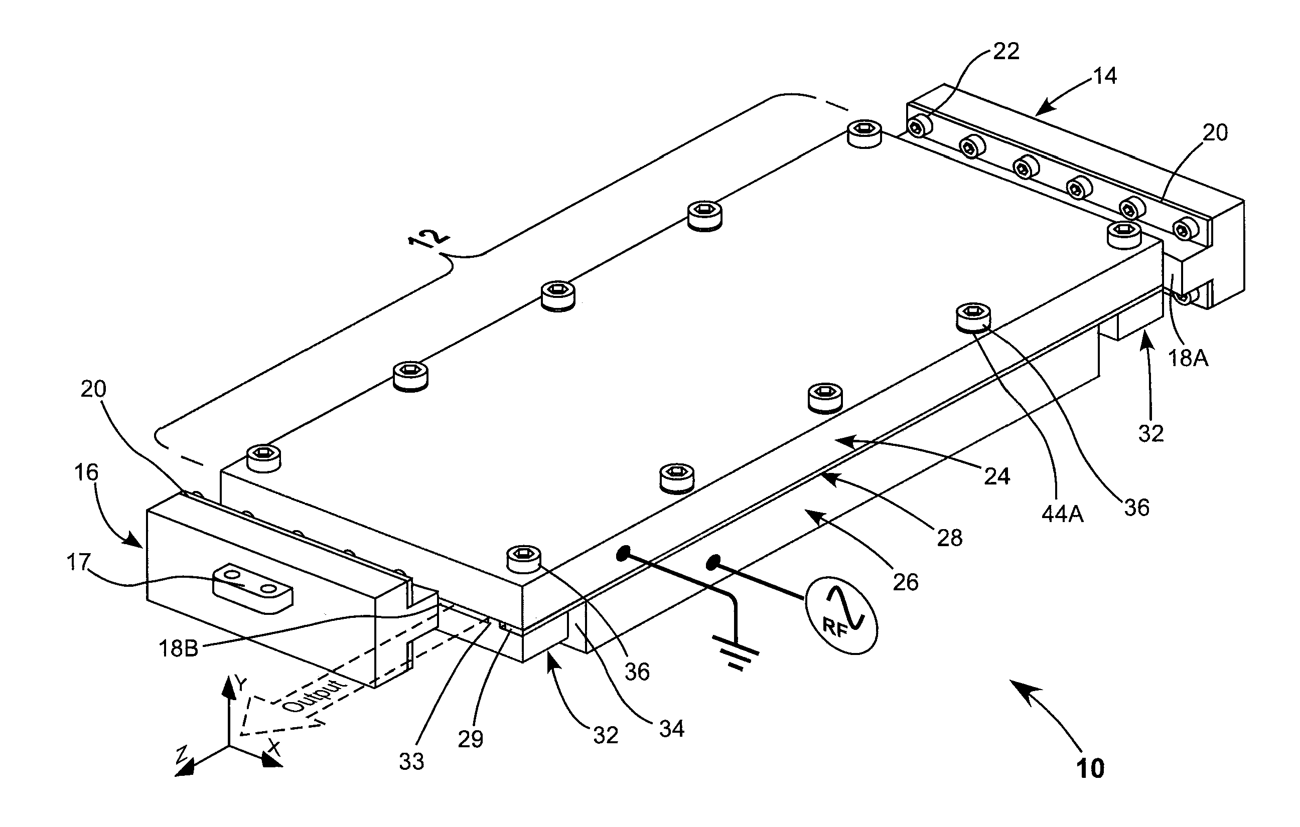
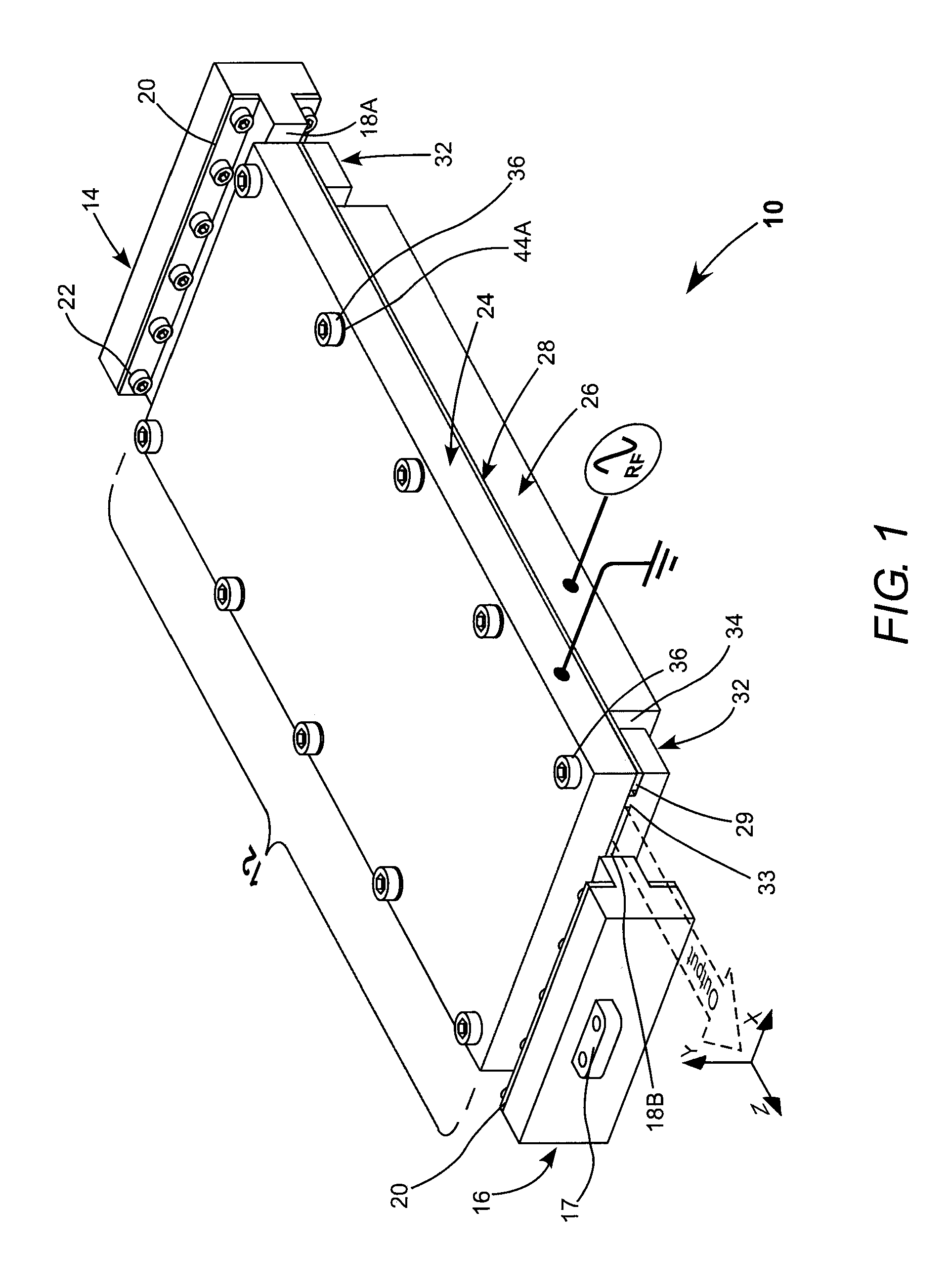
[0015]Referring now to the drawings, wherein like components are designated by like reference numerals, FIG. 1 schematically illustrates a CO2 slab-laser 10 including a discharge-electrode assembly 12 in accordance with the present invention. Cartesian axes X, Y, and Z are depicted, with Z being the propagation-axis of the resonator, and X and Y being the free-space and waveguide-axes respectively. Laser 10 includes a negative-branch unstable resonator formed in one axis (the X-axis) by mirror assemblies 14 and 16 having concave reflecting surfaces 18A and 18B, respectively. Reflective surface 18A provides the turning mirror surface of the unstable resonator. Reflective surface 18B is shorter in the X-axis to allow output radiation to be coupled out of the resonator as indicated.

[0016]In this example, the mirror-assemblies include an elongated mirror body having a T-shaped cross-section with the reflective surfaces being formed on the base of the stem of the “T”. Attached to the und...


PUM


Abstract

A CO2 gas discharge laser includes elongated planar live and ground electrodes vertically spaced and electrically insulated from each. The electrodes are spaced apart by ceramic spacer strips arranged along the edges of the electrodes. An auxiliary electrode is located at each end of the live electrode, co-planar with the live electrode, longitudinally spaced part from the live electrode vertically spaced apart from, but electrically connected to, the ground electrode. The auxiliary electrode has two raised portions spaced apart by a distance less than the distance between inside edges of the ceramic strips. The raised portions of the auxiliary electrode prevent erosion of the ceramic strips by laser radiation generated in the resonator when the laser is operating.

Description

PRIORITY[0001]This application claims priority to U.S. Provisional Patent Application Ser. No. 61 / 142,981 filed Jan. 7, 2009.TECHNICAL FIELD OF THE INVENTION[0002]The present invention relates in general to high-power CO2 (gas discharge) slab-lasers. The invention relates in particular to protecting resonator mirrors of such a laser from damage by particles generated during operation of the laser.DISCUSSION OF BACKGROUND ART[0003]A CO2 gas slab laser has two spaced-apart parallel rectangular electrodes separated by a relatively small distance. The electrodes are located in a housing containing a lasing gas mixture including carbon dioxide (CO2) and inert gases such as nitrogen (N2), helium (He) and xenon (Xe). Radio frequency (RF) power is applied to the electrodes and creates a gas discharge in the lasing gas mixture in the space (discharge region) between the electrodes. Ionized gas in the discharge region provides a gain medium of the laser.[0004]The optimum distance separating t...

Claims


Application Information

Patent Timeline
IPC IPC(8): H01S3/00H01S3/22
CPCH01S3/0315H01S3/0346H01S3/2232H01S3/0401H01S3/09713H01S3/038H01S3/03H01S3/0971
Inventor HUA, GONGXUE
Owner COHERENT INC
Learn More