Damping material, damping arrangement and method for designing a damping arrangement

a technology of damping arrangement and damping material, which is applied in the direction of reaction engines, mechanical equipment, machines/engines, etc., can solve the problems of large structure surfaces of wind turbines that vibrate and radiate noise, and the noise of tonal noise is undesirable, so as to achieve considerable tonal noise reduction, weight and cost, and optimize the effect of layou

Inactive Publication Date: 2007-11-20
GENERAL ELECTRIC CO
View PDF4 Cites 24 Cited by
  • Summary
  • Abstract
  • Description
  • Claims
  • Application Information

AI Technical Summary

Benefits of technology

[0016]The damping arrangement according to the above embodiment of the invention can be applied to vibrating metal surfaces, composite fiber reinforces plastic surfaces and hybrid concrete surfaces. Typically, the stripes are glued to the vibrating surface but can also be fixed by other means if required. Since only stripes of the laminate material are used, the damping arrangement is lightweight and its layout can be optimized with respect to the ratio of added mass versus damping performance. Furthermore, the stripes can be prefabricated separately and independently from the vibrating structure. Also, re-fitting of existing structures with a damping arrangement is possible. With the above described damping arrangement, considerable tonal noise reduction can be achieved. Especially, the damping arrangement can be specifically designed to damp only a few selected modes instead of global damping. Thus, an enormous amount of material, and therefore weight and costs, can be saved. Typically, the damping material comprises a soft viscoelastic layer having a shear modulus in the range of 105 N / m2 and 106 N / m2 and a stiff constrained layer made of metal. Alternatively, it is also possible to use only a stiff elastomeric material having a shear modulus of about 108 N / m2 without a constrained layer.
[0025]According to an embodiment of the present invention, only the most prominent acoustically radiating modes, usually between one and five modes, are selected for the design process. Typically, it is enough to increase damping only for these prominent structural modes that are efficient acoustic radiating modes to achieve a considerable reduction of tonal noise. Thus, a considerable amount of material, and therefore weight and costs, can be saved compared to a global damping approach.

Problems solved by technology

Noise emission from technical installations, particularly power systems, is a serious problem.
Furthermore, especially tonal noise is undesirable since it is penalized by regulations supported by the wind turbine sound measurement standard IEC-61400-11.
Mechanical noise is generated mainly from rotating machinery in the nacelle, particularly the gearbox and the generator, although there may also be contributions from cooling fans, auxiliary equipment (such as pumps and compressors), bearings and the yaw system.
Particularly, the high frequency dynamic forces in the power conversion steps induce large structure surfaces of wind turbines to vibrate and radiate noise.
The main structures of recent multi-megawatt wind turbines have larger and lighter surfaces which are increasingly sensitive to noise radiation because of low internal damping.
High frequency dynamic forces are significant in a frequency range of 20 Hz to 2 kHz where they are likely to generate audible tonal noise at a far distance when radiated by large wind turbine structures.
Mechanical noise may be transmitted through the system.
Noise is thus transferred to these structures; in addition there may be considerable resonance amplifications of the emitted sounds within the structure.
Thus, the gearbox is a source of significant tonal-mechanical noise.
Noise propagation through solid components, however, is much more difficult to prevent.

Method used


Image

  • Damping material, damping arrangement and method for designing a damping arrangement
  • Damping material, damping arrangement and method for designing a damping arrangement
  • Damping material, damping arrangement and method for designing a damping arrangement

Examples


Embodiment Construction

[0038]Reference will now be made in detail to the various embodiments of the invention, one or more examples of which are illustrated in the figures. Each example is provided by way of explanation of the invention, and is not meant as a limitation of the invention. For example, features illustrated or described as part of one embodiment can be used on or in conjunction with other embodiments to yield yet a further embodiment. It is intended that the present invention includes such modifications and variations.

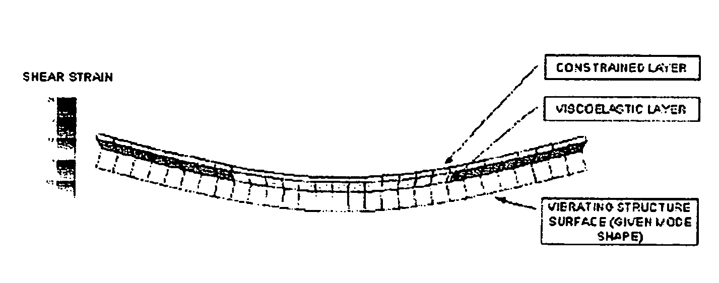
[0039]Damping of acoustically radiating modes can be achieved by a laminate material as it is shown in FIG. 1. Therein, a laminate material is adhered to a vibrating surface of a structure. The laminate material comprises a viscoelastic layer and a stiff constrained layer. Typically, the viscoelastic layer is formed of an elastomer based material and has a shear modulus of 105 N / m2 to 106 N / m2. In general, all elastomers having sufficient tensile and shear modulus can be used f...


PUM

PropertyMeasurementUnit
thicknessaaaaaaaaaa
thicknessaaaaaaaaaa
thicknessaaaaaaaaaa

Abstract

A laminate material for damping a vibrational mode of a structure is provided, the laminate material comprising a viscoelastic layer and a stiff constrained layer adhered to the viscoelastic layer, wherein the viscoelastic layer is elastomer based and the constrained layer is made of steel, galvanized steel or aluminum. Furthermore, a damping arrangement for damping at least one vibrational mode of a structure is provided, comprising a laminate material having a soft viscoelastic layer and a stiff constrained layer, wherein the laminate material is provided in the form of at least two longish stripes, the soft viscoelastic layer of the at least two stripes being adhered to a surface of the structure, and the at least two stripes being oriented at an angle of 0° to 180°, preferably 90°, with respect to each other.

Description

[0001]The present application claims priority to corresponding EP Application No. 04027321.1, filed on Nov. 17, 2004, the entire contents of which are hereby incorporated by reference.FIELD OF THE INVENTION[0002]The present invention relates to a damping material, a damping arrangement and a method for designing a damping arrangement, particularly to a damping material, a damping arrangement and a method for designing a damping arrangement used in wind turbines or related structures.BACKGROUND OF THE INVENTION[0003]Noise emission from technical installations, particularly power systems, is a serious problem. Legislation dictates the admissible sound pressure level that a noise source in a certain location may continuously make so that reduced noise immission is a key requirement for low impact environmental integration. Regulations governing these levels vary currently from country to country. In Europe, European Directives 2000-194-EC and 2002-49-EC provide standards. In Germany, t...

Claims


Application Information

Patent Timeline
Patent Type & Authority Patents(United States)
IPC IPC(8): F16F9/30F03D11/00
CPCB32B15/08B32B15/18B32B15/20B32B2419/00B32B2307/102B32B2307/51B32B2307/56B32B2250/02
Inventor BONNET
Owner GENERAL ELECTRIC CO
Why Eureka
Try Eureka