
Method for optimization of transmit and receive ultrasound pulses, particularly for ultrasonic imaging

a technology of ultrasonic transmission and ultrasonic imaging, which is applied in the field of optimizing ultrasonic transmit and receive pulses, can solve the problems of inability to achieve the effect of biomedical imaging, the structure of the body or object under examination is broken, and the homogeneity of the material is less,

Active Publication Date: 2007-11-20
ESAOTE
View PDF11 Cites 119 Cited by
  • Summary
  • Abstract
  • Description
  • Claims
  • Application Information

AI Technical Summary

Problems solved by technology

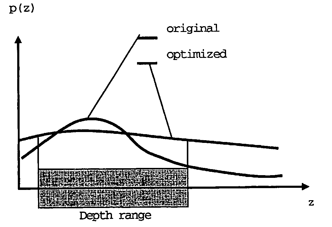
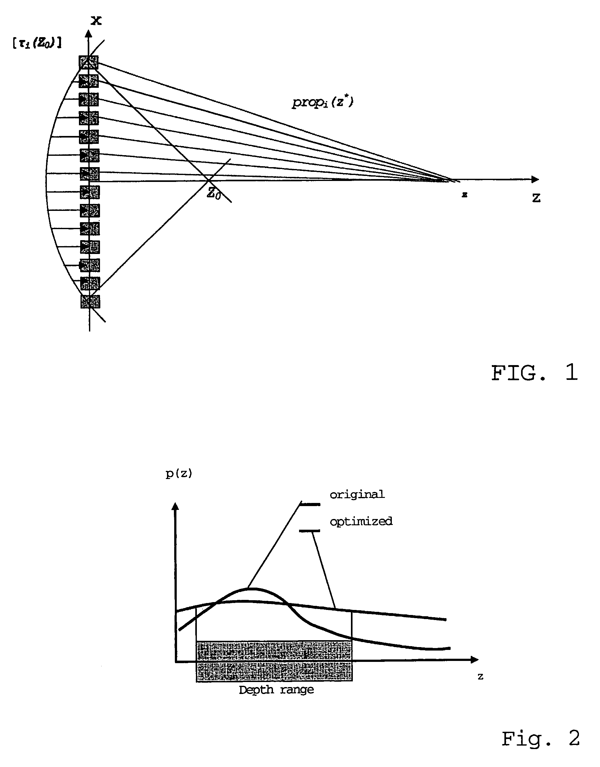
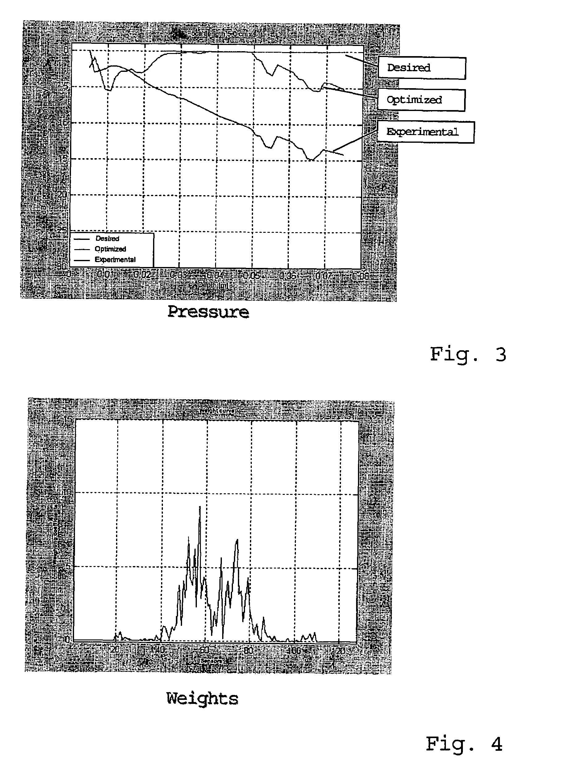
Nevertheless, in prior art no consideration is given to the problem that such optimization process does not account for the effects on mechanical pressure distribution in the body or object under examination, which is not optimal in itself, and becomes even less homogeneous in the focusing region, as a result of the ultrasonic pulse optimization process as described above.
The mechanical pressure that is exerted in the body or object being examined also has a certain importance, an excessive mechanical pressure potentially causing the structure of the material of the body or object under examination to break.
Such effect is particularly undesired in the field of biomedical imaging, the tissues of the body or object under examination being frequently permeated with contrast agents to enhance visibility of non echogenic tissues.
Contrast agents are particularly responsive to the mechanical pressure exerted by acoustic insonification pulses and may be destroyed when such mechanical pressure exceeds predetermined limits.
Since contrast agents may be located along a scan line at different positions as compared with the ultrasonic pulse focusing depth, prior art methods cannot ensure that the ultrasonic pulse has the right mechanical pressure in the area that is permeated with contrast agents, and it is further not easy to predict if such pressure will be lower or higher than the maximum allowed pressure to prevent contrast agent destruction.
Also, regarding the beam pattern, prior art methods cannot ensure that the latter will be constant or substantially constant or anyway that it will maintain a good quality as the penetration depth of the ultrasonic pulse within the body or object under examination changes.

Method used


Image

  • Method for optimization of transmit and receive ultrasound pulses, particularly for ultrasonic imaging
  • Method for optimization of transmit and receive ultrasound pulses, particularly for ultrasonic imaging
  • Method for optimization of transmit and receive ultrasound pulses, particularly for ultrasonic imaging

Examples


Embodiment Construction

[0030]The optimization goal for forming ultrasonic pulses is a compromise between the achievement of the best beam pattern and the achievement of the best mechanical pressure profile. Although there is not an exact mathematical solution, there certainly exists a best solution, wherein the energy function is minimized. Due to the considerable computational load required by the large number of variables, the optimal solution is obtained by using predictive or optimization algorithms of the stochastic or evolutionary type.

[0031]Suitable algorithms for this application are genetic algorithms, e.g., the Tabu search, among others. A particular algorithm that provides effective results, i.e., a relatively fast convergence and solution stability, where slight parameter variations with respect to the best solution generate slight result variations, is the Simulated Annealing algorithm.

[0032]This algorithm is described in “Genetic Algorithms in Search, Optimization and Machine Learning” by D....


PUM


Abstract

A method for optimizing transmit and receive ultrasound imaging pulses generates transmit pulses from an array of transducers which are energized by excitation signals that are applied to each individual transducer of the array. Each of the excitation signals are individually weighted to optimize the transducers' contribution to a predetermined energy function. Such optimization may also be performed on the received pulses.

Description

CROSS-REFERENCE TO RELATED APPLICATION[0001]The present application claims the benefit of Italian Application Serial No. IT SV2003A000023, filed on May 22, 2003, which is hereby incorporated by reference in its entirety.BACKGROUND OF THE INVENTION[0002]The invention addresses a method for optimizing ultrasonic transmit and receive pulses, particularly for ultrasound imaging, wherein transmit pulses are generated from ultrasonic pulse contributions of each of a plurality of electroacoustic transducers, which are grouped in an array and are individually triggered by electric excitation signals, the excitation signal being applied to each individual transducer of the array with a predetermined delay with respect to the application of the excitation signal to the other transducers, and a weight being applied to the excitation signal of each transducer for increasing / decreasing the amplitude of the excitation signal and, as a result, the acoustic signal generated by the transducer.[0003]...

Claims


Application Information

Patent Timeline
Patent Type & Authority Patents(United States)
IPC IPC(8): A61B8/00G10K11/34
CPCG10K11/34
Inventor TRUCCO, ANDREACURLETTO, SIMONE
Owner ESAOTE
Learn More