Cyclone dust collecting apparatus of vacuum cleaner

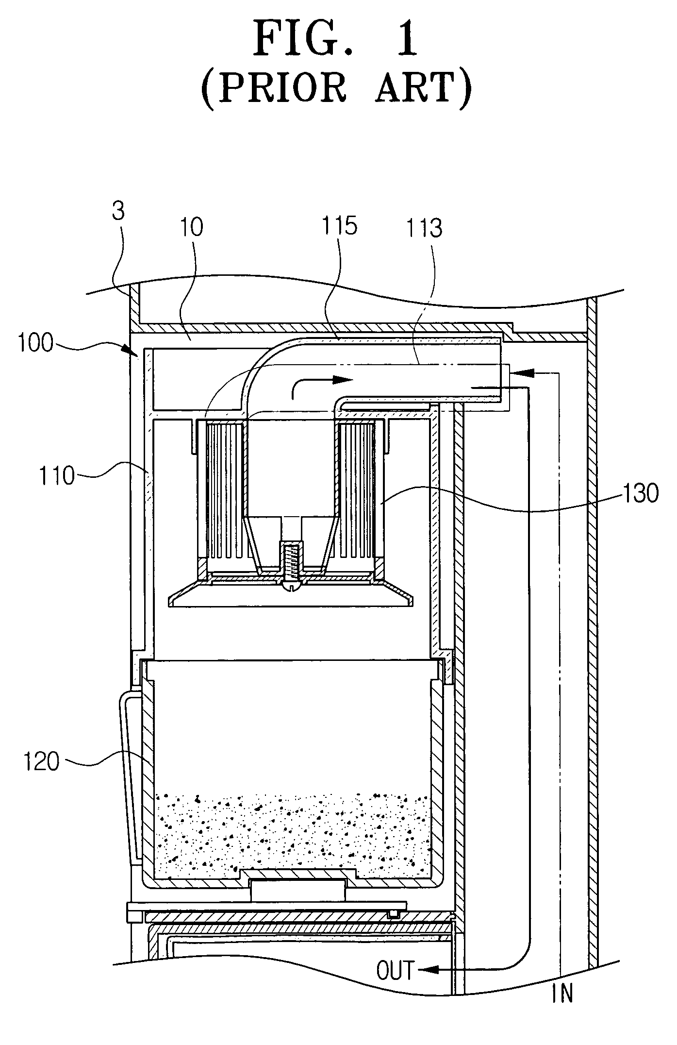
a vacuum cleaner and dust collector technology, applied in the direction of cleaning filter means, auxiliaries, separation processes, etc., can solve the problems of reducing the life span of each filter, generating noise, and single filter b>130/b> of the conventional cyclone dust collector cannot filter satisfactorily, so as to reduce the noise of the cleaner and the dust adhesion to the filter, the effect of efficient removal of dust and long life span

Active Publication Date: 2007-11-20
SAMSUNG GWANGJU ELECTRONICS CO LTD
View PDF6 Cites 24 Cited by
  • Summary
  • Abstract
  • Description
  • Claims
  • Application Information

AI Technical Summary

Benefits of technology

[0009]It is an object of the present invention, considering the above problems, to provide a cyclone dust collector to improve the capability of a vacuum cleaner, by separately collecting dust entrained in drawn in air in sequential steps in decreasing order of the dust particle size.
[0010]Another object of the present invention is to provide a cyclone dust collector for a vacuum cleaner that decreases noise and prevents adhesion of dust to a filter.
[0011]Yet another object of the present invention is to provide a cyclone dust collector for a vacuum cleaner that is superior in removing dust despite large amounts of dust being entrained in the drawn in air. Preferably, the inventive vacuum cleaner does not need frequent replacement of the filter, and has a long life span.
[0018]According to the present invention, there can be provided a cyclone dust collector of a vacuum cleaner which circulates the drawn in air in the lower and upper cyclone bodies, and separately collects the dust in sequence of the size thereof. Therefore, the dust collector according to the present invention efficiently removes dust regardless of the amount and has a longer life span since the filter does not have to be replaced often. Especially, according to the present invention, a noise of the cleaner and the dust adhering to the filter can be reduced.

Problems solved by technology

However, in the cyclone dust collector 100 of most conventional vacuum cleaners, dust, which is centrifugally separated and collected in the dust receptacle, is entrained and flows together with the rising air current, thereby generating noise when colliding with the filter 130.
In addition, a single filter 130 of the conventional cyclone dust collector cannot filter satisfactorily when there is a lot of dust in the drawn in air.
Therefore, the life span of each filter is significantly reduced, causing the concomitant inconvenience of requiring frequent replacement of filters.

Method used


Image

  • Cyclone dust collecting apparatus of vacuum cleaner
  • Cyclone dust collecting apparatus of vacuum cleaner
  • Cyclone dust collecting apparatus of vacuum cleaner

Examples


Embodiment Construction

[0028]Hereinafter, preferred embodiments of a cyclone vacuum cleaner according to the present invention will be described in detail with reference to the accompanying drawing figures.

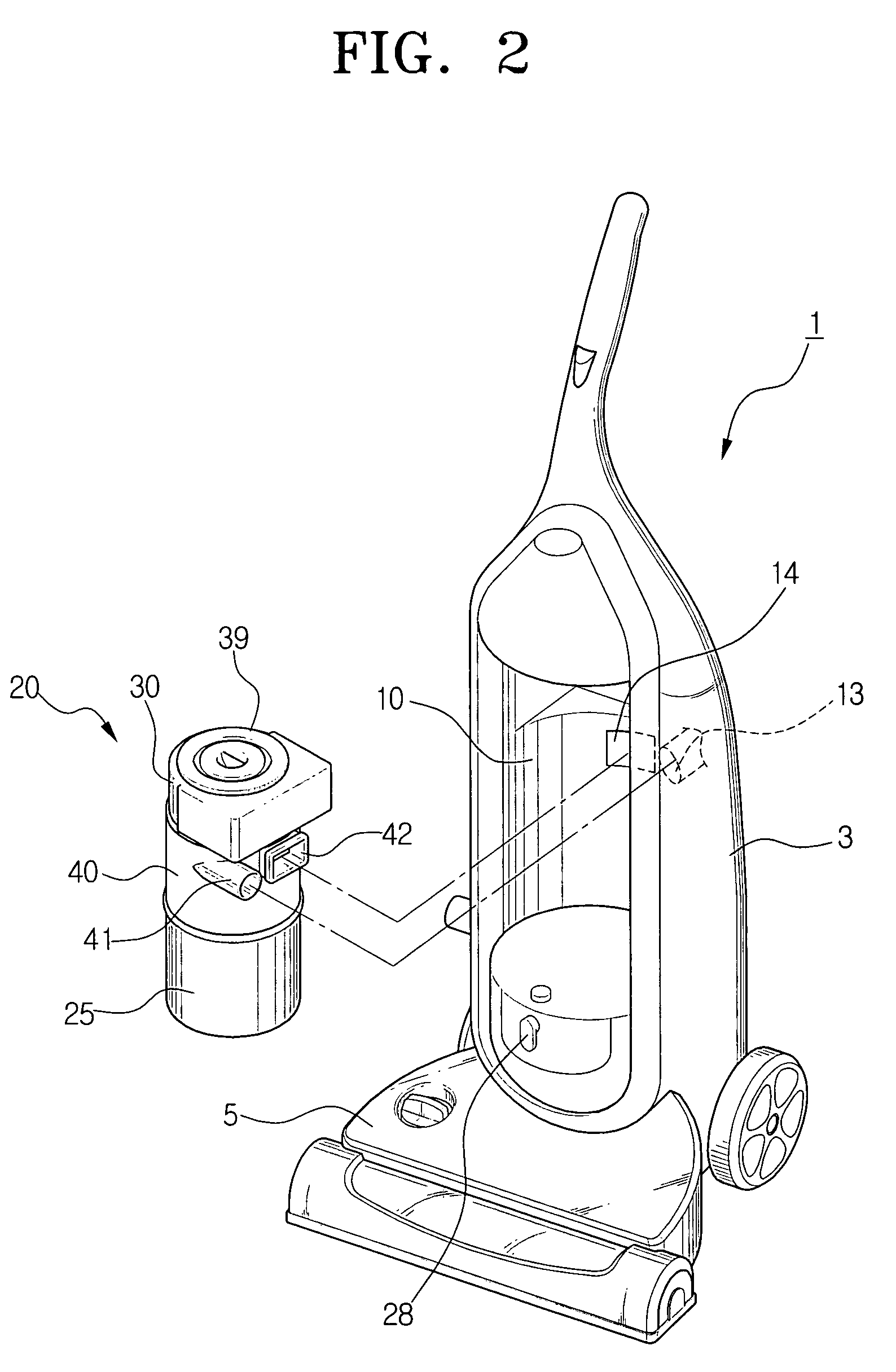
[0029]FIG. 2 is a perspective view of an upright type vacuum cleaner, comprising a cyclone dust collector according to the present invention. The upright cyclone vacuum cleaner 1 includes a main body 3 of the vacuum cleaner 1, and a cyclone dust collector 20, which is removably mounted on the main body 3.

[0030]In the main body 3, a vacuum generating device (not shown) is mounted, and in a lower part of the main body 3, a suction brush 5 is mounted vacuuming dust by means of an external air flow. A device receiving chamber 10 is available for receiving the cyclone dust collector 20. The chamber 10 comprises an indent disposed in the center of the main body 3 for removably receiving the cyclone dust collector 20. On the rear side of the device receiving chamber 10, a suction connection port 13 (shown in p...


PUM

PropertyMeasurementUnit
centrifugal forceaaaaaaaaaa
timeaaaaaaaaaa
forceaaaaaaaaaa

Abstract

A cyclone dust collector of a vacuum cleaner includes a lower cyclone body for initially separating dust entrained in air drawn in through an air suction port, an upper cyclone body for separating fine dust entrained in the air that has been initially filtered in the lower cyclone body, and a central air path for guiding the air which is filtered in the upper cyclone body along a center axis line, and discharging the air through an air discharge port in the lower cyclone body. The capability of the vacuum cleaner can be improved by circulating the drawn in air having the entrained dust in the lower and upper cyclone bodies, and separately and sequentially collecting the dust at least partially based on the particle size thereof.

Description

BACKGROUND OF THE INVENTION[0001]1. Field of the Invention[0002]The present invention relates generally to a cyclone dust collector of a vacuum cleaner, and more particularly, to a cyclone dust collector for collecting dust and dirt entrained in an air stream (hereinafter, referred to as ‘dust’) by centrifugally separating the same several times in successive, sequential steps.[0003]2. Description of the Related Art[0004]As shown in FIG. 1, which is a partially enlarged vertical section of a cyclone dust collector of a conventional vacuum cleaner, the general conventional cyclone dust collector comprises a cyclone body 110 and a filter 130 mounted in the cyclone body 110. In a device receiving unit 10 of a cleaner body 3 of FIG. 2, the cyclone dust collector 100 is mounted. Referring to FIG. 2, the following elements are disposed at the rear side of the device receiving unit 10: an air suction connection port 13 (shown in phantom) for drawing in air including entrained dust; and an ...

Claims


Application Information

Patent Timeline
Patent Type & Authority Patents(United States)
IPC IPC(8): B01D45/12A47L5/28A47L9/00A47L9/06A47L9/12A47L9/16A47L9/19B04C5/00
CPCA47L5/28A47L9/127A47L9/19A47L9/1666Y10S55/03Y10S55/34A47L9/16B04C5/00
Inventor LEE, BYUNG-JO
Owner SAMSUNG GWANGJU ELECTRONICS CO LTD
Why Eureka
Try Eureka