

Cross-flow filtration cassettes and methods for fabrication of same
a technology of filtration cassettes and cross-flow filtration, which is applied in the direction of membranes, other chemical processes, separation processes, etc., can solve the problems of not being able to perform filtration, and achieve the effect of increasing the active filter surface area and high-efficiency sealing spa
Inactive Publication Date: 2007-11-20
SILICON VALLEY BANK
View PDF12 Cites 5 Cited by
- Summary
- Abstract
- Description
- Claims
- Application Information
AI Technical Summary
Benefits of technology
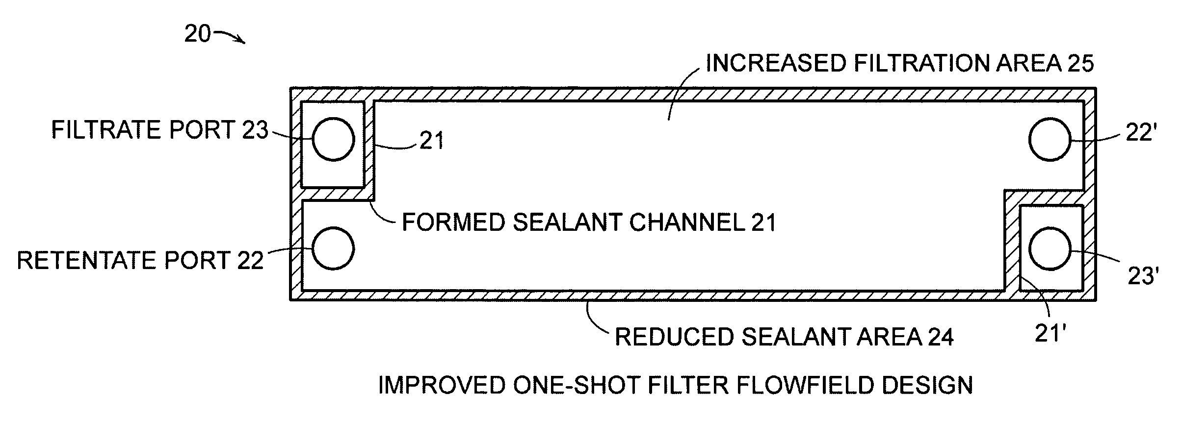
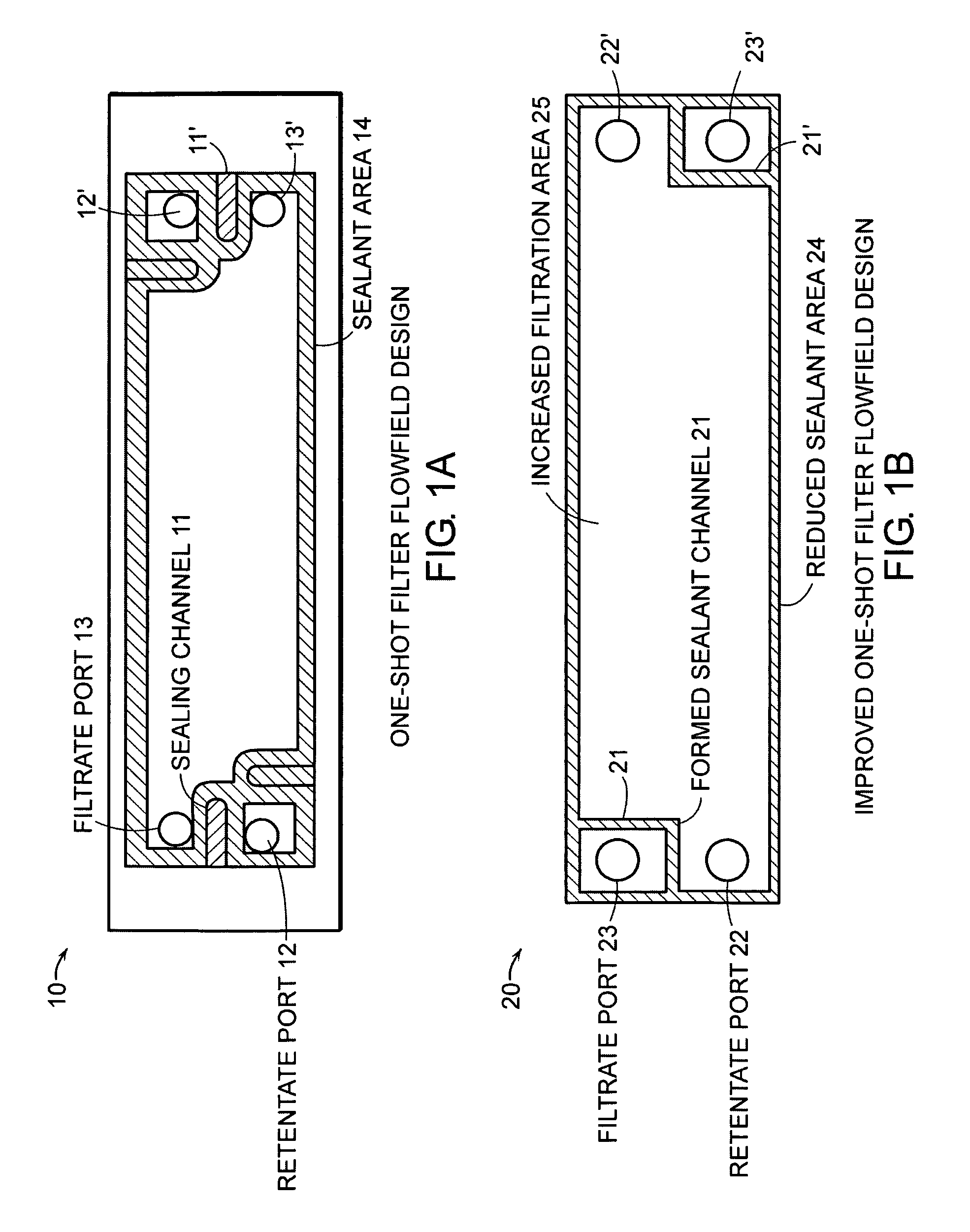
[0011]The present invention provides substantially improved filtration cassettes with an increased active filter surface area and a highly efficient sealing space. Utilizing methods of the invention, a precise vacuum (or pressure) is not required to achieve repeatable sealing geometry within the cassettes.
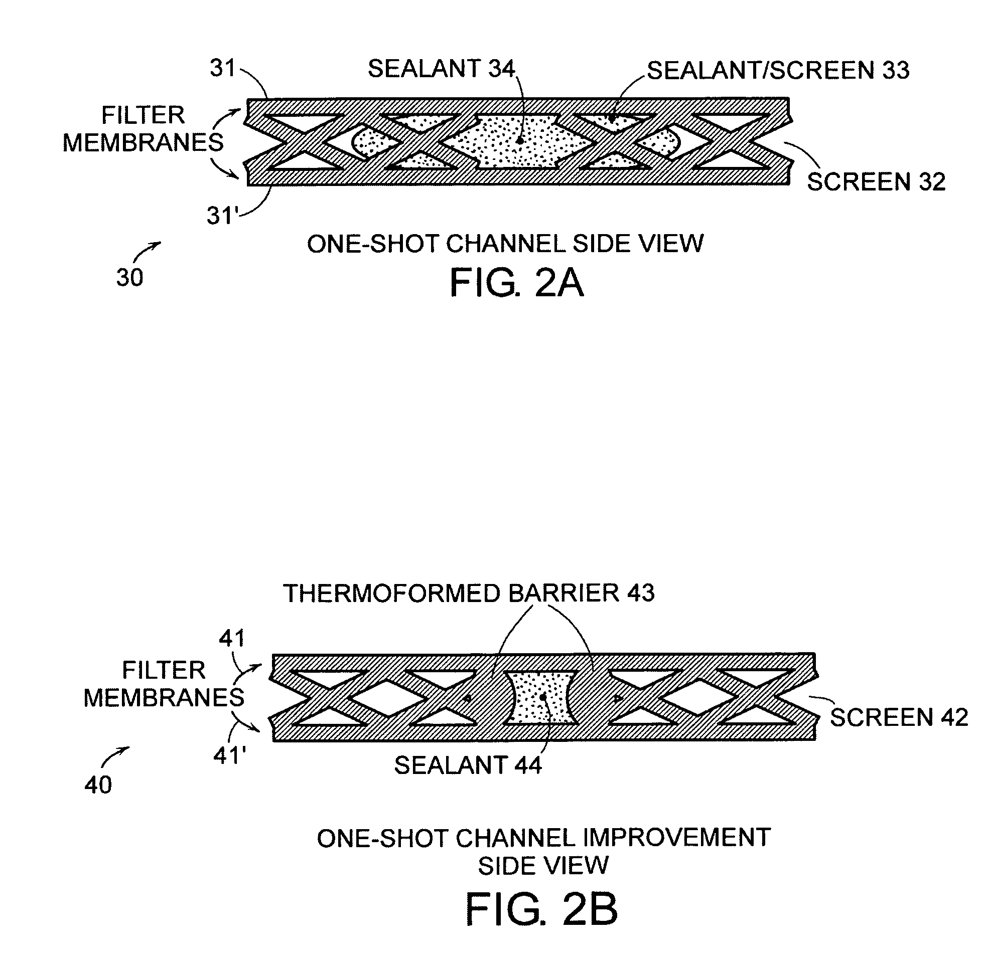
[0012]The present invention builds on our own innovation described in WO 03 / 080226. As reported therein, sealant flow can be controlled by cutting channels in screen-based flow fields. In that way, sealant flows preferentially where the screen has been cut away (to the desired port, e.g., retentate port or filtrate port). However, utilizing that design some sealant will still flow, albeit at a reduced rate, into the screen flow field. This flow into the screen creates a large area filled by sealant which consequently is not usable for filtration. Increased filtration area is particularly desirable, for example, in that it decreases filtration time for any given process.
[0013]According to the present invention, sealing channels are made in the screen not by a cutting process, but by a forming operation that creates side-walls for precisely controlling the flow of the sealant. In contrast to cassettes and methods of the prior art, temperature and / or pressure are used in the present invention to form sealing channels and associated barriers on either side of the channels. In preferred embodiments of the invention, sealing channels are formed by pressing the screen in a heated die, or using an ultrasonic welding horn, hot / heated knife, laser device or the like, to produce the desired geometry. As the skilled artisan will appreciate, using methods of the invention, there are a number of ways to produce a variety of suitable channel geometries with formed barriers on either side of the channels to achieve optimal performance in the sealing process.
[0014]The present invention allows for the fabrication of filtration cassettes with a minimum of labor and at a reduced cost. Cassettes and methods of the invention also are well suited for process automation.
Problems solved by technology
However, utilizing that design some sealant will still flow, albeit at a reduced rate, into the screen flow field.
This flow into the screen creates a large area filled by sealant which consequently is not usable for filtration.
Method used
View moreImage
Smart ImageViewing Examples

Examples
example
[0048]Channels can be cut in polyester or polypropylene mesh stock with a hot knife, whereby the edges of the material are simultaneously melted to create the barriers about the sealing channel. The fabrication of the filtration cassette would directly follow the example in WO 03 / 080226; however the sensitivity to exact time and pressure during the vacuum forming process would be considerably less.
Login to View More PUM
| Property | Measurement | Unit |
|---|---|---|
| temperature | aaaaa | aaaaa |
| pressure | aaaaa | aaaaa |
| shape | aaaaa | aaaaa |
Abstract
This invention relates generally to filtration cassettes, and, more particularly to methods of fabricating cross-flow filtration cassettes. Cassettes of the invention are characterized, in part, by a series of sealing channels which selectively seal the filtrate and retentate ports to prevent undesired flow. The sealing channels have formed barriers on either side thereof which create side-walls for precisely controlling the flow of the sealant during the cassette formation. Filtration cassettes of the present invention can be manufactured from conventional membrane and flow screen components and can utilize both injection molding and vacuum assisted resin transfer molding fabrication processes.
Description
[0001]This application is a continuation of provisional application U.S. Ser. No. 60 / 515,995, filed Oct. 31, 2003.BACKGROUND OF THE INVENTION[0002]1. Field of the Invention[0003]This invention relates generally to filtration cassettes, and, more particularly to methods of fabricating cross-flow filtration cassettes. Cassettes of the invention are characterized, in part, by a series of sealing channels which selectively seal the filtrate and retentate ports within the cassettes and prevent undesired flow. Methods of the invention produce filtration cassettes with an increased active filter surface area. Additionally, the present invention allows for the fabrication of filtration cassettes with a minimum of labor and at a reduced cost.[0004]2. Background[0005]Filtration cassettes are used in a variety of biotechnology and food processing applications. These cassettes typically comprise a stacked assembly of porous membrane components and filtrate and retentate flow screen components. ...
Claims
Login to View More Application Information
Patent Timeline
 Patent Type & AuthorityPatents(United States)
IPC IPC(8): B01D63/00B05C5/02B01D61/00B01D63/08B01D65/00
CPCB01D63/081B01D63/082B01D65/003B01D2313/44Y10S264/48B01D2313/04
InventorOSENAR, PAULSABIN, PAUL
OwnerSILICON VALLEY BANK