Electric supply apparatus

a technology for electrical supplies and cables, applied in the direction of cables, cable arrangements between relatively moving parts, coupling device connections, etc., can solve the problem of difficulty in utilizing the different kinds of protective tubes at the same tim

Inactive Publication Date: 2007-11-20
YAZAKI CORP
View PDF16 Cites 16 Cited by
  • Summary
  • Abstract
  • Description
  • Claims
  • Application Information

AI Technical Summary

Benefits of technology

[0012]The present invention is to provide an electric supply apparatus having a wiring harness protected against outer interferences and rain water, having a small and compact protector, giving a higher flexibility of a wiring harness in the protector, and having a long lifetime of the wiring harness.
[0014]Thereby, the wiring harness is bent in a small diameter so that the protector is formed smaller. The rigid protective member is arranged from the protector inside a sliding door to the vehicle body to protect the electric cables inside the wiring harness from outside interferences or rain water. The flexible and rigid protective members are connected to each other with the spring holder. The spring holder fastens the both protective members and is fixed to the leaf spring. When the rigid protective member is pulled from outside, the tension is exerted on the leaf spring so that the flexible protective member is not subjected to the excess tension. A corrugated tube or thick vinyl tube is utilized for the rigid protective member and a thin vinyl tube is utilized for the net tube.
[0026]The both protective members are connected to each other at a loop portion of the wiring harness through the spring holder. Thereby, when the wiring harness is pulled, the loop portion has a smaller diameter against a bias of the leaf spring and expands outwardly with a restoring force of the leaf spring so as to absorb a sag of the wiring harness. The biasing force of the leaf spring is directly transferred to the protective tubes through the spring holder so that the wiring harness expands and contracts with the spring holder without slipping.

Problems solved by technology

It is quite difficult to utilize the different kinds of the protective tubes at the same time.

Method used


Image

  • Electric supply apparatus
  • Electric supply apparatus
  • Electric supply apparatus

Examples


Embodiment Construction

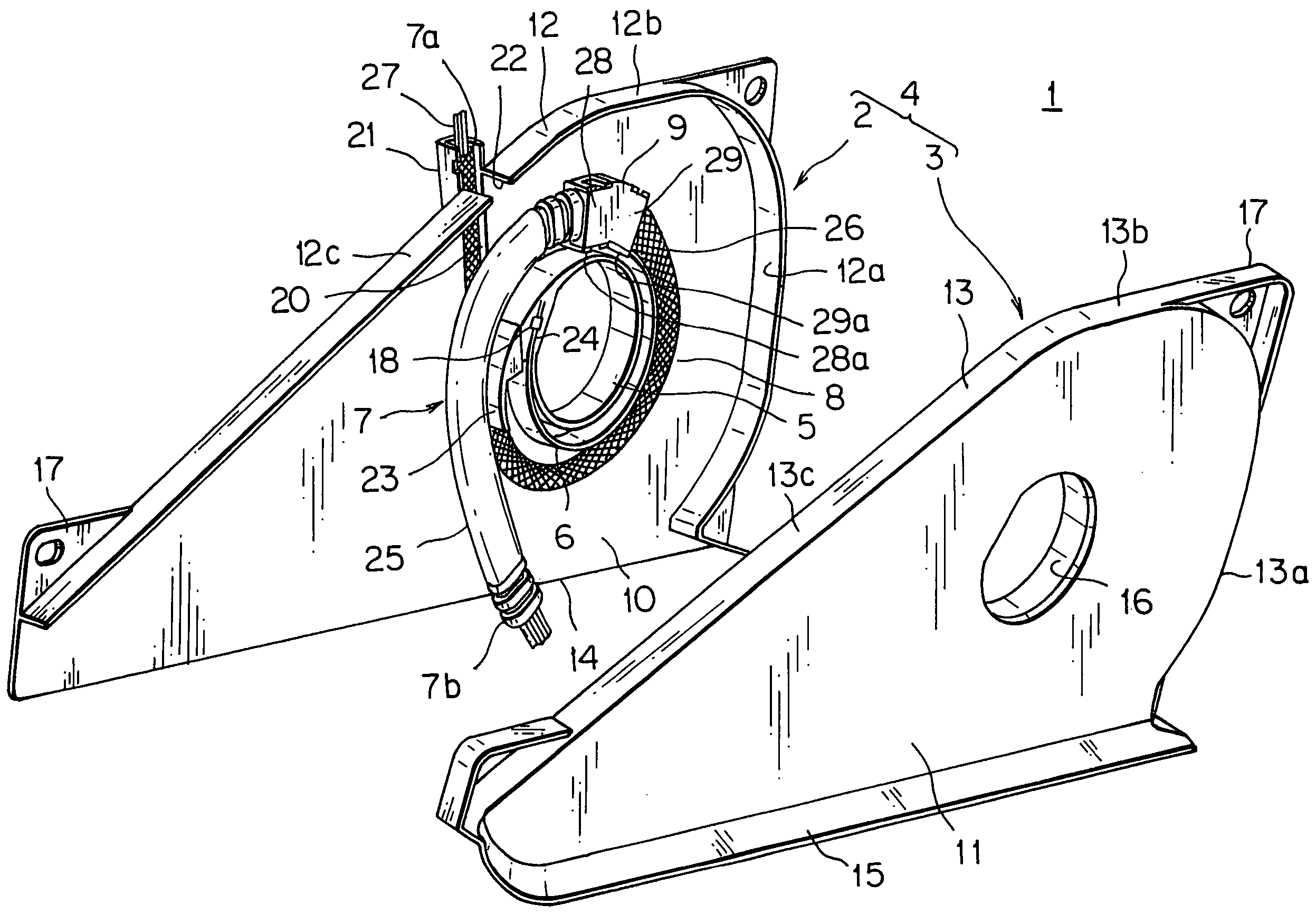
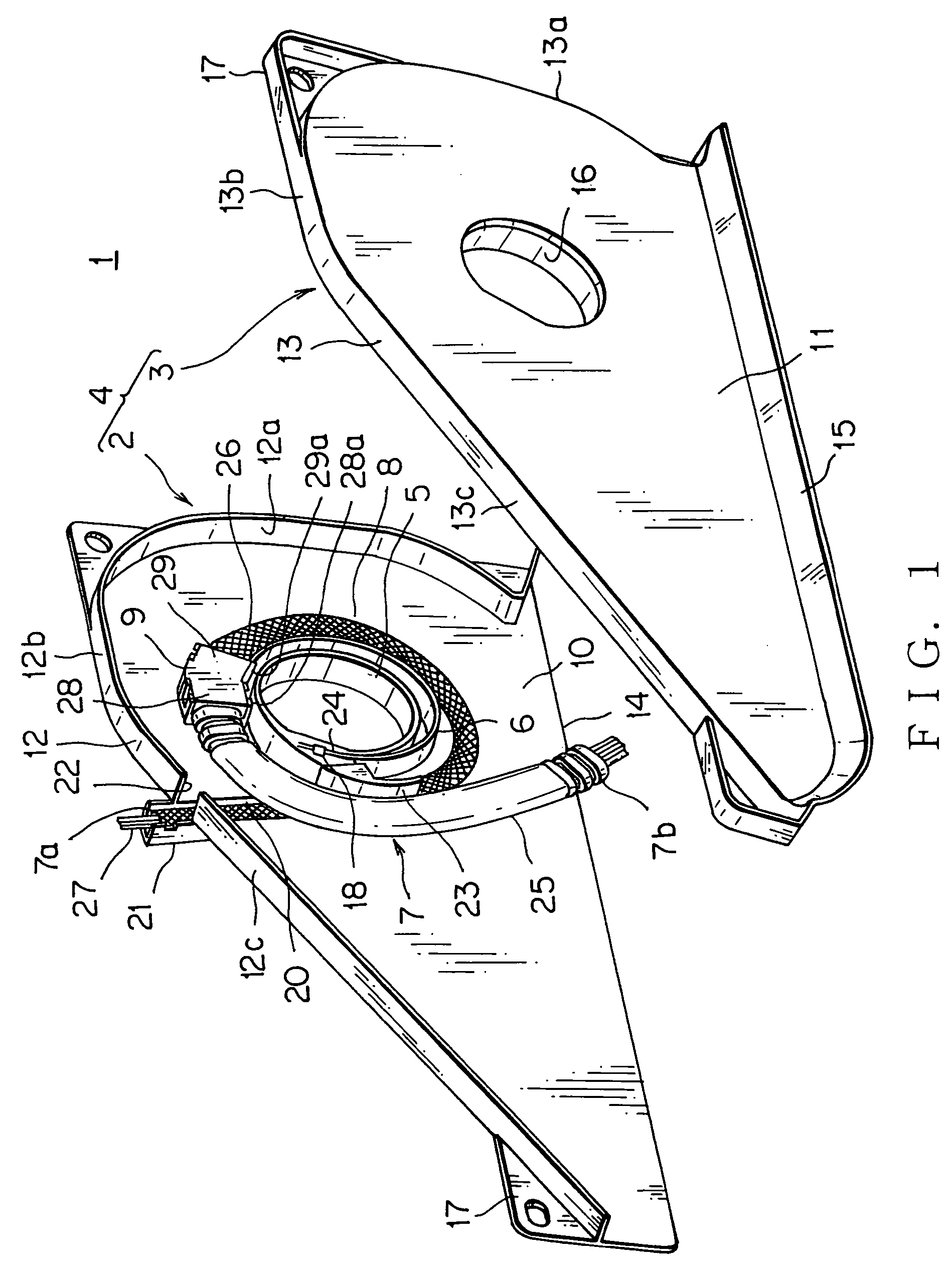
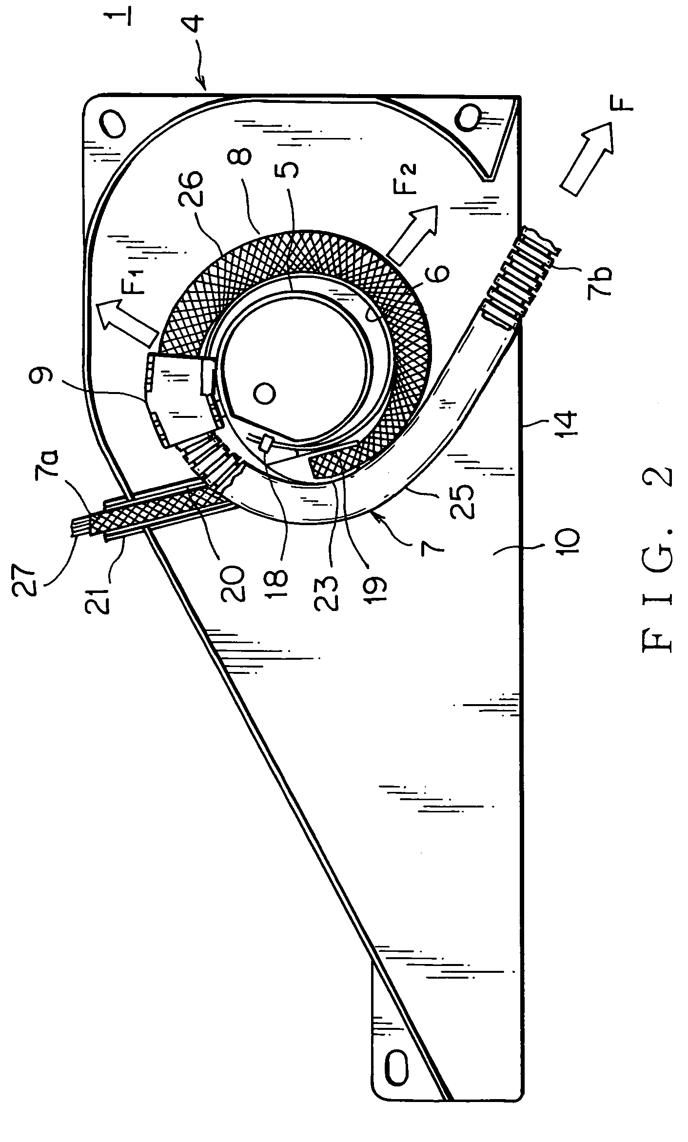
[0047]FIGS. 1-4 show an embodiment of an electric supply apparatus according to the present invention.

[0048]The electric supply apparatus 1, as shown in FIG. 1, includes a protector 4 having a base 2 and a cover 3 made of a synthetic resin, a leaf spring 6, being made of a metal, wound flexibly around an annular wall 5 disposed inside the base 2, a wiring harness 7 covered with a corrugated tube (rigid protective member or protective tube) 25 at one side and a net tube (flexible protective member or protective tube) 26 at the other side, and arranged around the annular wall 5 to form a loop portion 8, and a spring holder 9, being made of a synthetic resin and holding a front end portion of the leaf spring 6, for fastening a middle portion of the wiring harness 7 in a longitudinal direction, or a part of the loop portion 8 for connecting the corrugated tube 25 and the net tube 26 each other. The electric supply apparatus 1 is mounted to a sliding door, not shown, of a motor vehicle.

[...


PUM

PropertyMeasurementUnit
flexibleaaaaaaaaaa
rigidityaaaaaaaaaa
lengthaaaaaaaaaa

Abstract

The present invention is to provide an electric supply apparatus having a wiring harness bent freely in a protector and prevented from outer interferences or rain water. An electric supply apparatus having a wiring harness includes a protector, a leaf spring disposed in the protector and a spring holder fixed to the leaf spring, wherein the spring holder holds one end portion of a flexible protective member of the wiring harness and one end portion of a rigid protective member of the wiring harness, and wherein the flexible protective member is disposed along the leaf spring and the rigid protective member is arranged from the spring holder to an opening for leading out the wiring harness. The flexible protective member has an insertion member at the one end portion, the insertion member is resin-molded with the flexible protective member and fixed to one side portion of the spring holder. The spring holder has protrusions penetrating into the flexible protective member and engaging with grooves of the rigid protective member.

Description

BACKGROUND OF THE INVENTION[0001]1. Field of the Invention[0002]The present invention relates to an electric supply apparatus having a wiring harness being bent freely in a protector and urged by a leaf spring to absorb sag thereof.[0003]2. Description of the Related Art[0004]FIGS. 19 and 20 are an embodiment of a conventional electric supply apparatus, for example, JP, 2002-17032,A (page 4, FIGS. 4-5).[0005]The electric supply apparatus 50 is disposed in a sliding door 41 of a motor vehicle. The electric supply apparatus 50 has a protector 42 (a cover is not shown), which is made of a synthetic resin, receiving a wiring harness 43 flexibly, and a metal leaf spring 44 to urge the wiring harness 43 upwardly in the protector 42.[0006]A lower end portion of the leaf spring 44 is fixed to a forward and lower portion of the protector 42 together with the wiring harness 43. A front end portion of the leaf spring 44 supports the wiring harness 43 slidably. The front end portion of the leaf...

Claims


Application Information

Patent Timeline
Patent Type & Authority Patents(United States)
IPC IPC(8): H02G3/04H01B7/00
CPCH02G11/00B60R16/0215
Inventor WATANABE, NORIOKOGURE, NAOTO
Owner YAZAKI CORP
Why Eureka
Try Eureka