Eureka AIR delivers breakthrough ideas for toughest innovation challenges, trusted by R&D personnel around the world.

Echo cancellation in a communication device

a communication device and echo cancellation technology, applied in the field of communication devices, can solve the problems of affecting the reception of received signals, and affecting the reception of received signals, and reducing the echo reduction from 15.0 to 20.0 db to provide sufficient echo cancellation

Inactive Publication Date: 2007-11-20
MACOM TECH SOLUTIONS HLDG INC
View PDF4 Cites 14 Cited by
  • Summary
  • Abstract
  • Description
  • Claims
  • Application Information

AI Technical Summary

Benefits of technology

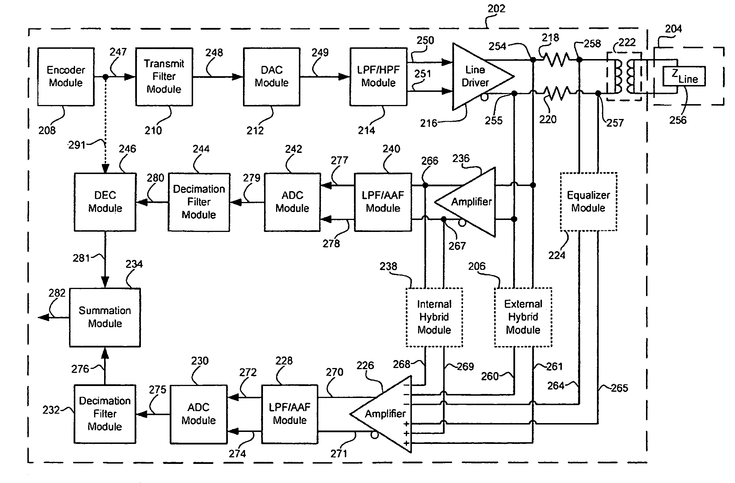
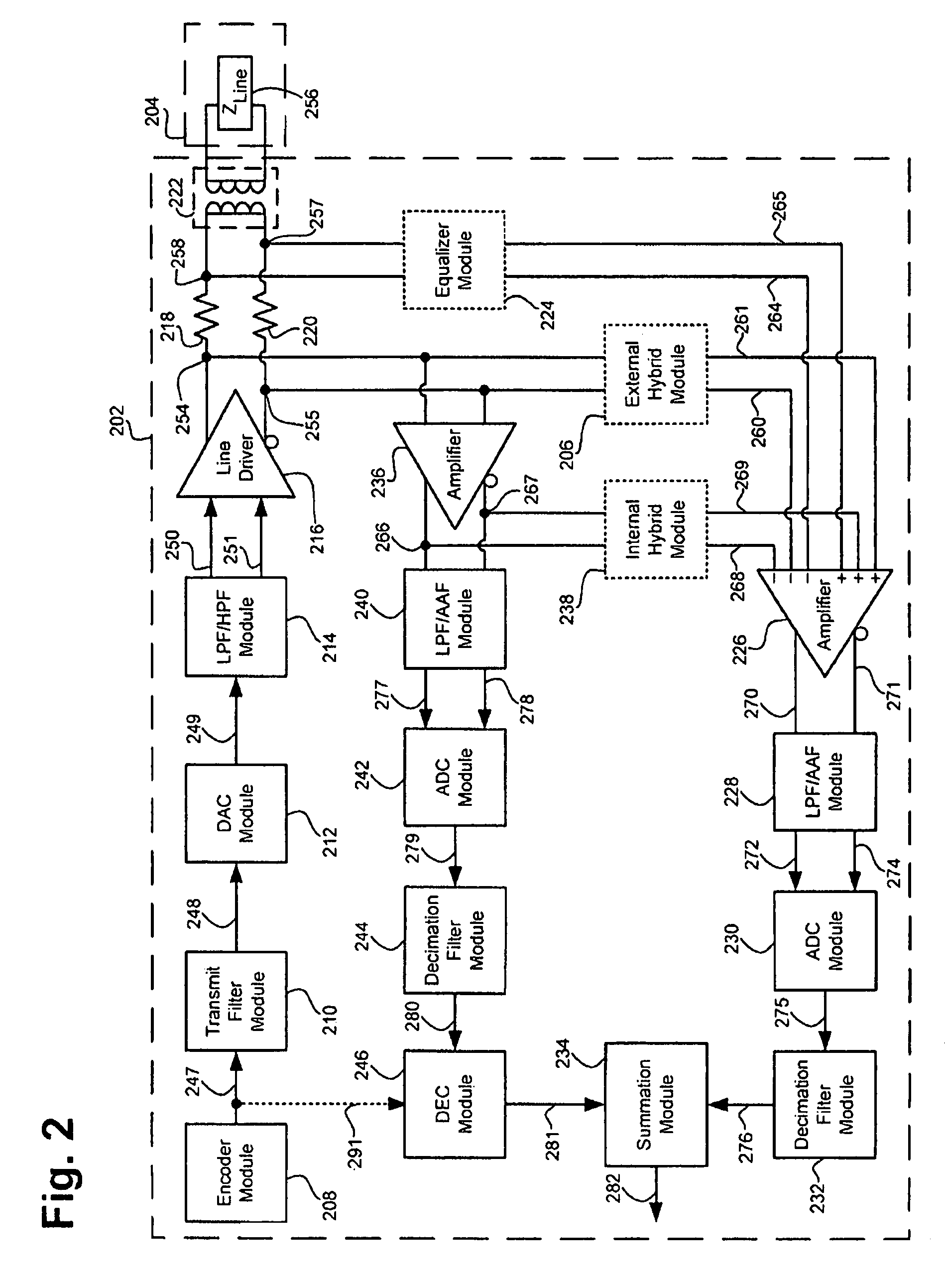
[0013]According to this exemplary embodiment, the communication device further comprises a summation module coupled to the digital echo canceller module, where the summation module receives the echo cancellation signal and the composite signal, and where the composite signal comprises a received signal and the linear and non-linear echo components. The summation module is configured to subtrac

Problems solved by technology

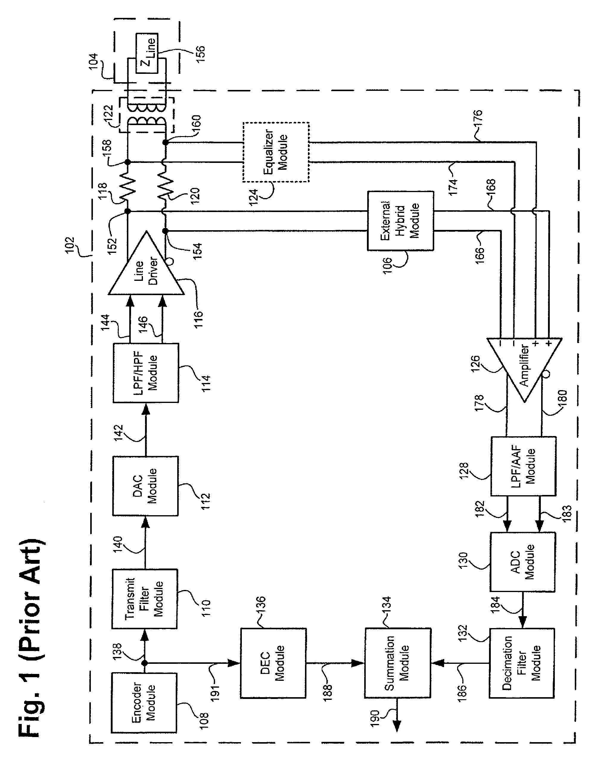
As a result, the signal transmitted by a line driver in the DSL modem can encounter discontinuities in the line, which can cause part of the transmitted signal to reflect or echo back and interfere with a received signal.
Thus, since the signal strength of the received signal can be approximately 80.0 dB below the signal strength of the transmitted signal, an echo reduction of 15.0 to 20.0 dB does not provide sufficient echo cancellation for proper reception of the received signal.
However, very accurate components are costly and matching the impedance of the line to a required degree of accuracy is difficult to achieve.
During actual operation, the signal transmitted by the line driver includes non-linear signal components, since linearity is difficult to achieve in a high power and high current device such as a line driver.
Thus, the unattenuated portion of the non-linear component of the echo will be passed through to the decoder portion of the DSL modem as noise, which can undesirably interfere with reception of low level signals.
Although the DEC could be designed to cancel the non-linear portion of the echo, the complexity of the DEC would be greatly increased, since an exponentially increasing amount of digital circuitry would be required for each harmonic of the non-linear portion of the echo.
As a result, the cost of the DEC would be undesirably increased.

Method used


Image

  • Echo cancellation in a communication device
  • Echo cancellation in a communication device
  • Echo cancellation in a communication device

Examples


Embodiment Construction

[0016]The present invention is directed to echo cancellation in a communication device. The following description contains specific information pertaining to the implementation of the present invention. One skilled in the art will recognize that the present invention may be implemented in a manner different from that specifically discussed in the present application. Moreover, some of the specific details of the invention are not discussed in order not to obscure the invention.

[0017]The drawings in the present application and their accompanying detailed description are directed to merely exemplary embodiments of the invention. To maintain brevity, other embodiments of the present invention are not specifically described in the present application and are not specifically illustrated by the present drawings.

[0018]FIG. 1 shows a block diagram of an exemplary DSL modem, including a conventional exemplary echo cancellation system, coupled to a line. Conventional DSL modem 102 in FIG. 1 ...


PUM


Abstract

According to one exemplary embodiment, a communication device comprises a line driver, where the line driver provides an output signal. The communication device further comprises a digital echo canceller module coupled to the line driver, where the digital echo canceller module receives an echo reference signal determined by the output signal of the line driver, where the echo canceller module outputs an echo cancellation signal, and where the echo cancellation signal is capable of canceling linear and non-linear components of a composite signal. The communication device further comprises a summation module coupled to the digital echo canceller module, where the summation module receives the echo cancellation signal and the composite signal, and where the composite signal comprises a received signal and the linear and non-linear echo components. The summation module is configured to subtract the echo cancellation signal from the composite signal and to output the received signal.

Description

BACKGROUND OF THE INVENTION[0001]1. Field of the Invention[0002]The present invention is generally related to the field of communication devices. More particularly, the present invention is related to echo cancellation in communication devices.[0003]2. Related Art[0004]The increasing demand for high-speed Internet connectivity has in turn increased the demand for various communication devices such as modems, and in particular for modems utilizing digital subscriber line (“DSL”) technology which provides high-speed transmission of voice, video, and data information over existing copper telephone lines. Although the DSL modem is used merely as an example in the present application to illustrate shortcomings of the existing art, such shortcomings and the solutions set forth by the present invention, are also applicable to other communication devices.[0005]DSL technology utilizes a DSL modem to achieve data speed from 128 Kbps to 8 Mbps and higher over an ordinary telephone line. During...

Claims


Application Information

Patent Timeline
IPC IPC(8): H04B3/20
CPCH04B3/23H04L25/0272H04B3/03H04L27/2626H04L25/028
Inventor JARCY, MICHAEL J.
Owner MACOM TECH SOLUTIONS HLDG INC
Why Eureka
Eureka Blog
Learn More