Imaging tomography apparatus with multiple operating modes

a tomography and operating mode technology, applied in tomography, instruments, applications, etc., can solve the problem that the field of application of this tomography apparatus is thereby limited to the imaging of the heart, and achieve the effect of optimizing the method

Inactive Publication Date: 2007-11-20
SIEMENS HEALTHCARE GMBH
View PDF6 Cites 26 Cited by
  • Summary
  • Abstract
  • Description
  • Claims
  • Application Information

AI Technical Summary

Benefits of technology

[0005]An object of the present invention is to remedy the disadvantages according to the prior art as represented by the above-described apparatus. In particular an optimally universally usable imaging tomography apparatus should be specified. It is a further object of the invention to provide an optimally simple method for changing the operating mode of such a tomography apparatus.
[0006]This object is achieved in accordance with the invention, having first and second x-ray radiators and a detector arrangement with a first detector and a second detector, wherein at least the first detector can be reversibly moved along a circumferential track of the measurement device of the gantry, relative to the second detector. It is thereby possible to position the detectors according to the requirements of a current operating mode selected for the tomography apparatus. A change between two operating modes of the tomography apparatus can be achieved by a reversible movement of at least the first detector, i.e. a movement of the detector in a forward direction or back direction. For example, no detectors need to be provided exclusively for one operating mode. It is thereby possible to reduce the total number of measurement channels of the detectors. The measurement channels of the detectors of the detector means can be optimally utilized. In particular it is possible to arrange the detectors such that all measurement channels for the detection of radiation can be used for every provided operating mode of the tomography apparatus. The acquisition and / or the processing of the measurement data can clearly be simplified significantly. For example, the data rate in the transfer of the measurement data to a data processing device can be reduced due to the lower number of measurement channels. In particular, no differentiation or filtering of used and unused measurement channels needs to ensue. Furthermore, the weight of the detector arrangement as well as the cost of the tomography apparatus can be reduced due to a lower number of measurement channels.

Problems solved by technology

The field of application of this tomography apparatus is thereby limited to imaging the heart.

Method used


Image

  • Imaging tomography apparatus with multiple operating modes
  • Imaging tomography apparatus with multiple operating modes
  • Imaging tomography apparatus with multiple operating modes

Examples


Embodiment Construction

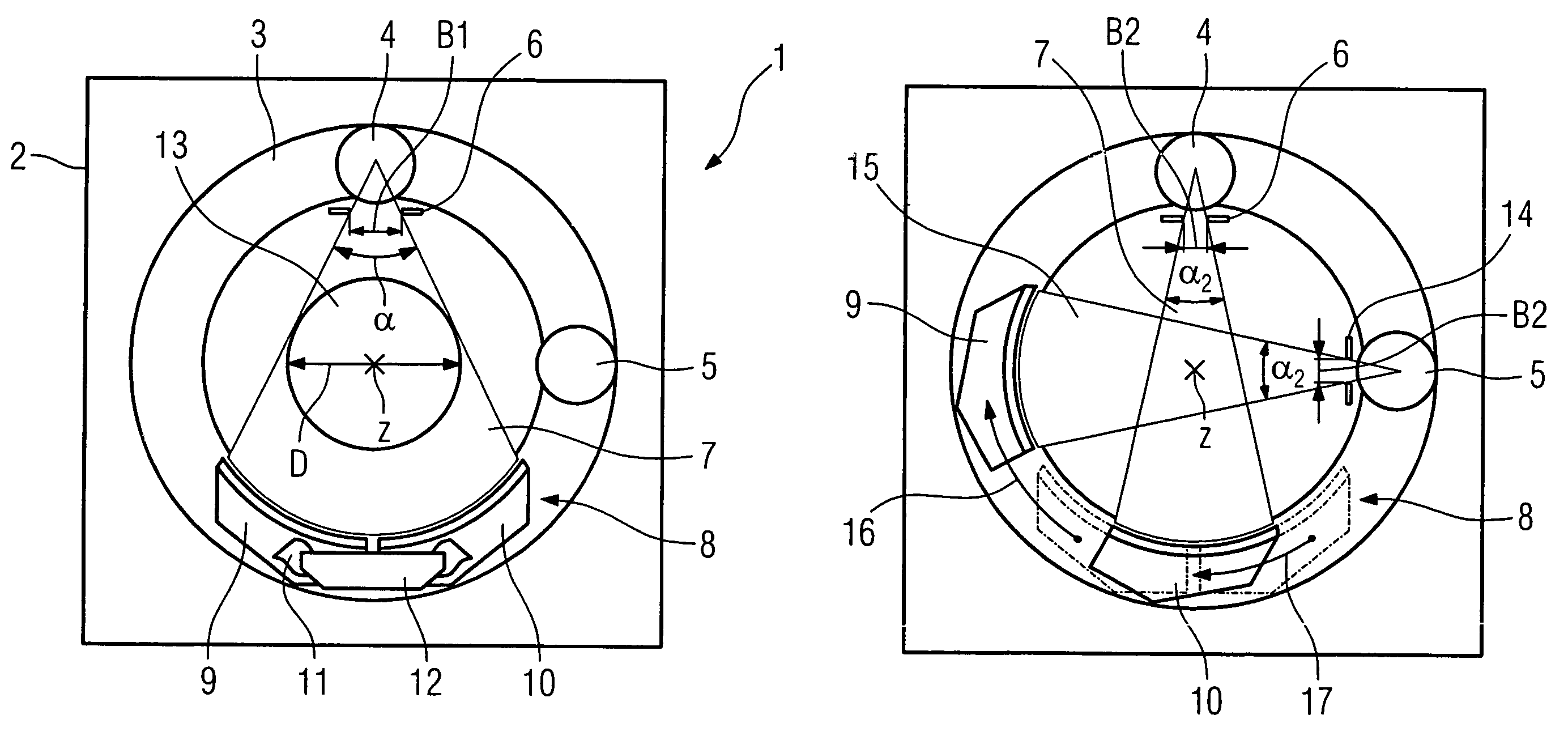
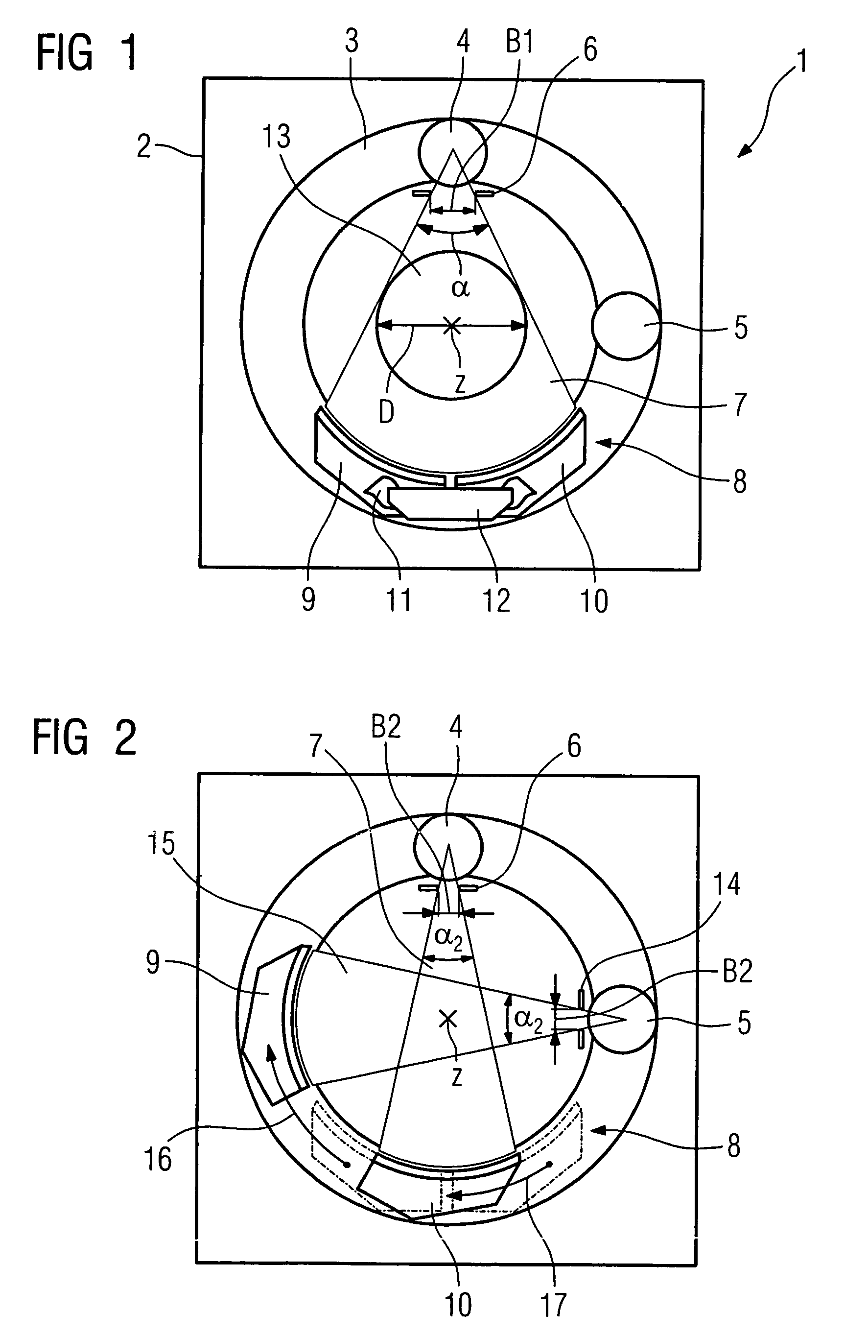
[0028]The inventive computed tomography apparatus in a first measurement position is shown in FIG. 1. A gantry (designated with the reference character 1) of the apparatus has a stationary part 2 and a part 3 that can rotate around a fixed z-axis z. A first x-ray tube 4 and a second x-ray tube 5 are mounted on the rotatable part 3 offset from one another by an angle of approximately 90° with regard to the z-axis z. A diaphragm mounted on the first x-ray tube 4, with a variable first diaphragm aperture B1, is designated with the reference character 6. A fan-shaped x-ray beam 7 with an aperture angle α originates from the first x-ray tube 4. A detector arrangement 8 is located on the rotatable part 3 of the gantry 1 in the beam path of the first x-ray beam 7 opposite the first x-ray tube 4. The detector means 8 has a first detector 9 and a second detector 10 disposed adjacent to one another. The first detector 9 and the second detector 10 are connected with flexible lines 11 with a da...


PUM

PropertyMeasurementUnit
angleaaaaaaaaaa
diameteraaaaaaaaaa
angleaaaaaaaaaa

Abstract

An imaging tomography apparatus with multiple operating modes has at least two radiators from which x-ray radiation emanates. The tomography apparatus has a radiation detector arrangement with a first detector and a second detector. At least the first detector can be reversibly moved relative to the second detector along a circumferential track of the measurement device of the gantry.

Description

BACKGROUND OF THE INVENTION[0001]1. Field of the Invention[0002]The invention concerns an imaging tomography apparatus as well as a method for changing the operating mode of the tomography apparatus.[0003]2. Description of the Prior Art[0004]A tomography apparatus for imaging the heart is known from U.S. Pat. No. 6,421,412. This known tomography apparatus has a number of detector-radiator pairs. These are mounted offset from one another by a fixed angle around the z-axis. The geometry of the arrangement of each detector-radiator pair cannot be changed. In contrast to a conventional x-ray computed tomography apparatus, this tomography apparatus has smaller detectors and thus a smaller field of view, for example 200 mm as opposed to 500 mm. The field of application of this tomography apparatus is thereby limited to imaging the heart.SUMMARY OF THE INVENTION[0005]An object of the present invention is to remedy the disadvantages according to the prior art as represented by the above-des...

Claims


Application Information

Patent Timeline
Patent Type & Authority Patents(United States)
IPC IPC(8): G01N23/083A61B6/00A61B6/03
CPCA61B6/032A61B6/4085A61B6/4014A61B6/4021
Inventor POPESCU, STEFAN
Owner SIEMENS HEALTHCARE GMBH
Why Eureka
Try Eureka