Electrically controlled pressure relief valve and system and method for controlling same

a technology of electrical control and pressure relief valve, which is applied in fluid pressure control, process and machine control, instruments, etc., can solve the problems of reducing system compliance or inertia, and affecting the operation of the valve step response,

Active Publication Date: 2007-11-20
GENERAL KINETICS ENG CORP
View PDF7 Cites 83 Cited by
  • Summary
  • Abstract
  • Description
  • Claims
  • Application Information

AI Technical Summary

Problems solved by technology

While such electrically controlled pressure relief valves provide performance advantages, such as safety and known set pressure nearly independent of flow, there may also be disadvantages.
Existing electrically controlled pressure relief valves may be unstable or may have a very long response time.
The instability can be attributed to the interaction of the output pressure variation of the valve with other hydraulic system components such as the hydraulic compliance in the system or the inertia of the hydraulic fluid running in the hoses.
To mitigate the instabil

Method used


Image

  • Electrically controlled pressure relief valve and system and method for controlling same
  • Electrically controlled pressure relief valve and system and method for controlling same
  • Electrically controlled pressure relief valve and system and method for controlling same

Examples


Embodiment Construction

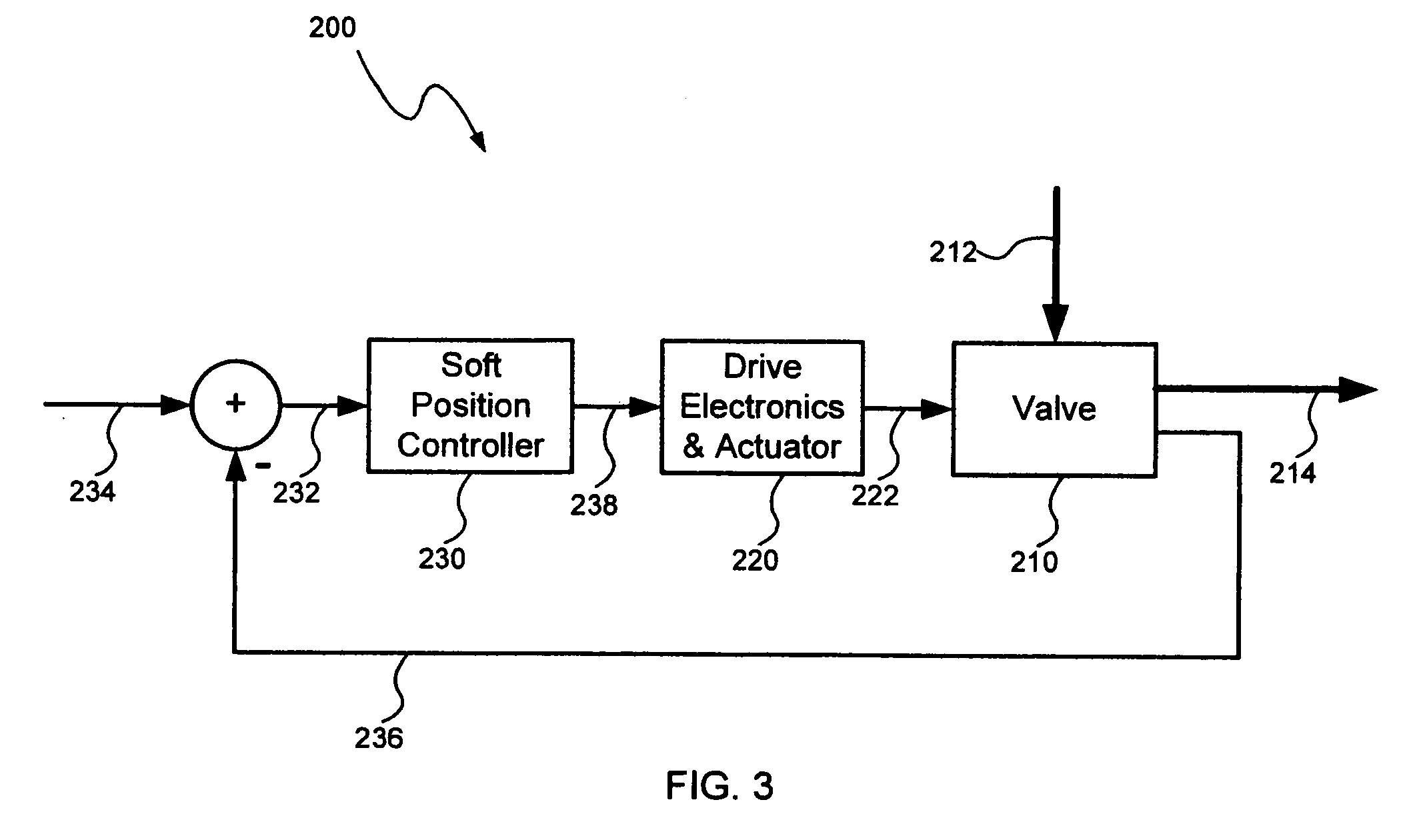
[0019]An electrically controlled pressure relief valve, consistent with embodiments of the present invention, is capable of delivering high speed performance to pressure relief and pressure control applications. In general, a valve control system and method may use a soft position control loop to control the position of the electrically controlled pressure relief valve. The electrically controlled pressure relief valve may also incorporate a tunable pressure term by shaping the valve orifice to improve stability and by shaping the valve orifice to uniformly distribute the effective bandwidth over the valve operating range. The electrically controlled pressure relief valve may also have a tunable default or failure mode, which allows the valve to continue operation with desired operating characteristics in the event of a loss of power.

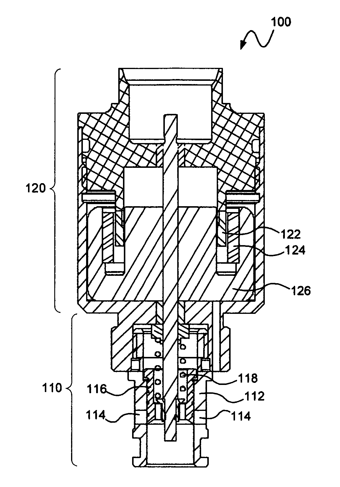
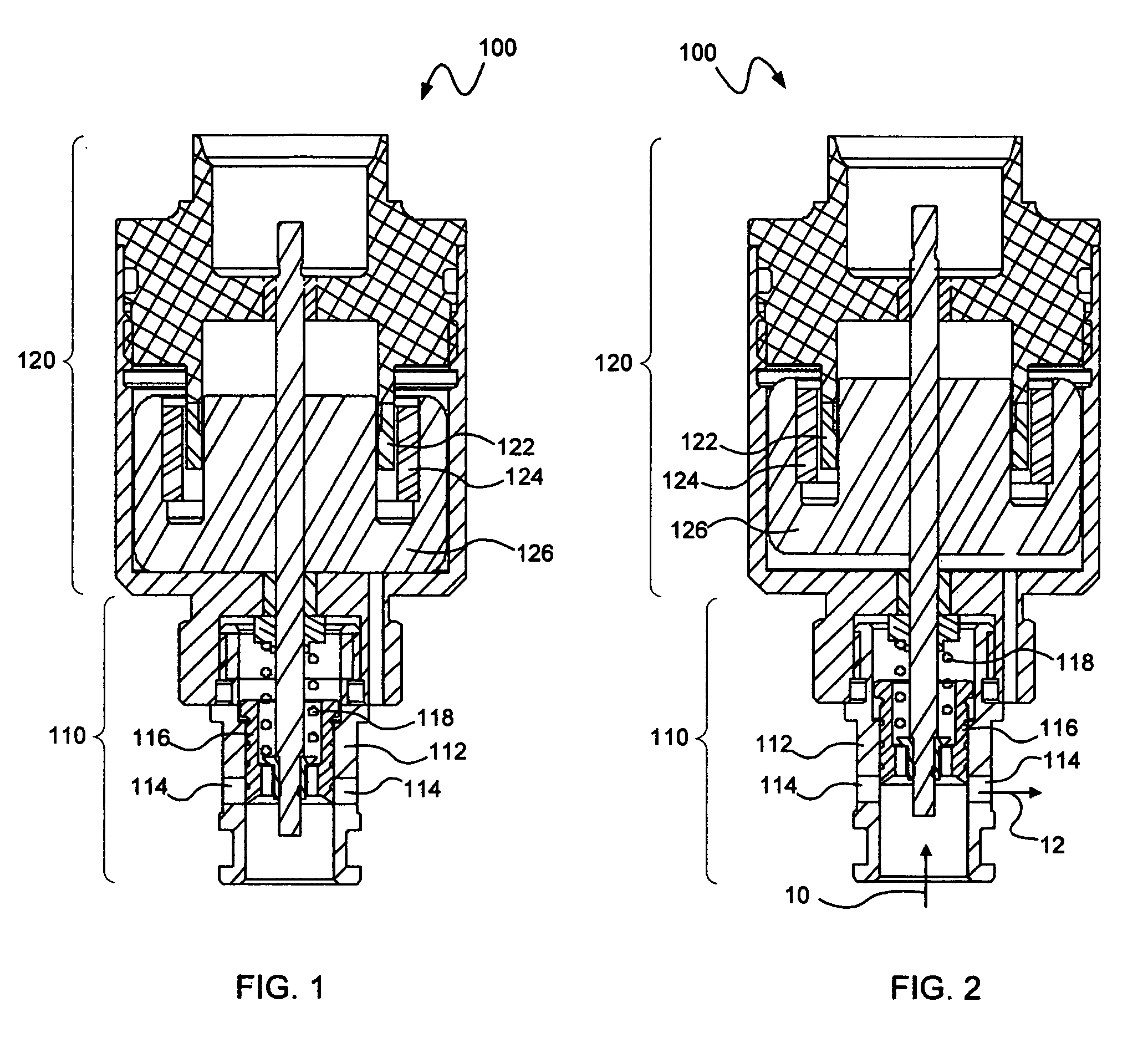
[0020]Referring to FIGS. 1 and 2, an electrically controlled pressure relief valve 100, according to an exemplary embodiment, may include a valve porti...


PUM


Abstract

A system and method for controlling an electrically controlled pressure relief valve may use a soft position control loop to control the position of the valve. A pressure relief valve may also include a modified orifice shape to improve stability, to uniformly distribute the effective bandwidth over the valve operating range, and to provide a tunable default mode.

Description

CROSS-REFERENCE TO RELATED APPLICATIONS[0001]This application claims the benefit of co-pending U.S. Provisional Patent Application Ser. No. 60 / 624,636, filed on Nov. 3, 2004, which is fully incorporated herein by reference.FIELD[0002]This disclosure relates to controllable valves and more particularly, to a system and method for controlling an electrically controlled pressure relief valve.BACKGROUND[0003]In general, a pressure relief valve may be designed to open at a specific pressure to prevent pressures in a system from exceeding certain limits. Pressure relief valves are widely used in a variety of applications. Pressure relief valves may be used for the purpose of providing safe operation in high pressure environments, for example, in hydraulic systems. Pressure relief valves may also be used to establish a known pressure for the purpose of providing control over a process, flow or motion. One example of an application for a pressure relief valve is a shock absorber application...

Claims


Application Information

Patent Timeline
IPC IPC(8): G05D11/00G05D9/00
CPCF16K17/02F16K31/06G05D16/2013F16K31/0689F16K31/0668G05D16/2022Y10T137/0396
Inventor LAPLANTE, JOHNLARKINS, WILLIAM T.
Owner GENERAL KINETICS ENG CORP
Why Eureka
Try Eureka