Method and apparatus for estimating of fluid contamination downhole

a technology of fluid contamination and method, applied in the field of method and apparatus for quantifying fluid contamination, can solve the problems of fluid sample purity, sample is still not at 100% purity, and does not provide quantitative value, so as to improve the fit to data and improve the fit to pulses

Inactive Publication Date: 2007-11-20
BAKER HUGHES INC
View PDF7 Cites 25 Cited by
  • Summary
  • Abstract
  • Description
  • Claims
  • Application Information

AI Technical Summary

Benefits of technology

[0012]In a first aspect of the present invention, a method and apparatus are provided that fit fluid measurement data to a non-asymptotic curve. One example of a non-asymptotic curve is a curve (e.g., a power series approximation), which provides an improved fit to the data over the typical pumping time and, which can also be successfully extrapolated to several times that pumping time, but which approaches plus or minus infinity at infinite times. Another example of a non-asymptotic curve is an equation that has an oscillatory component such as a sine wave, which never reaches a fixed limit. The sine wave can be adjusted in frequency, phase and amplitude to provide an improved fit to pulses in the monitored response that are associated with each stroke of the pump. In a third aspect of the invention, a method and apparatus are provided that perform pattern recognition of a straight line to a best fit of the measured data in log-log space.
[0014]The method and apparatus of the present invention can use a data-fitting equation such as log(1−ftp)=(−p)log(t)+log(A1 / A0), which is the equation of a straight line that has no (Y=constant) asymptote, except for the meaningless case of p=0. The method and apparatus perform a series of regressions using different estimates of A0 but do not actually calculate A0, itself. For example, one can start with the current value, A, at a time t, as the first estimate of A0, then proceed to a slightly higher value of A+ε, then to an even higher value of A+2ε, and so on. The A0 value for which the fit to the measured data is closest to the shape of a straight line (based on the highest coefficient of determination, or R-squared value) then becomes the best estimate of an A0 value. In a third aspect the method and apparatus of the present invention a method and apparatus are provided that fit a differentiable curve to measurement data or physical property data derived from the measurement data. The present invention then estimates ftp from the ratio of (dA / dt) to A. In a fifth aspect of the present invention a method and apparatus are provided that fit an asymptotic curve to difference of two responses such as the difference of two absorbances associated with different wavelengths (optical channels) rather than to an absorbance itself. Using an absorbance difference removes the baseline offsets caused by passing sand particles or bubbles.

Problems solved by technology

Measuring these properties of the fluid therefore provides qualitative insight into a fluid sample's purity but does not provide a quantitative value, fp, for the fluid sample's purity.
Thus, even though a downhole measured property (OD, etc.) has substantially stopped changing, the sample is still not at 100% purity.
On the other hand, if by pumping for a very long time, it is possible to achieve only slightly better contamination level, an operator ends up wasting very expensive rig time and also risks the very costly possibility of allowing a tool to become stuck in the wellbore.
Clearly, an assumption of a sample clean rate of t−5 / 12 can be rigid and inapplicable to real time situations.
Another problem with monitoring sample clean up over time by looking at optical absorption over time is that sand particles and other particulates can cause considerable scattering, which causes the absorption values measured over time to “jump” and appear noisy.

Method used


Image

  • Method and apparatus for estimating of fluid contamination downhole
  • Method and apparatus for estimating of fluid contamination downhole
  • Method and apparatus for estimating of fluid contamination downhole

Examples


first embodiment

[0039]In the present invention, the method and apparatus of the present invention fit fluid measurement data to a non-asymptotic curve. One example of a non-asymptotic curve is a curve which provides an improved fit to the data over the typical pumping time and, which can also be successfully extrapolated to several times that pumping time, but which approaches plus or minus infinity at infinite times, such as a power series approximation. Another example of a non-asymptotic curve is an equation that has an oscillatory component such as a sine wave, which never reaches a fixed limit. The sine wave can be adjusted in frequency, phase and amplitude to provide an improved fit to pulses in the monitored response that are associated with each stroke of the pump.

[0040]In a second embodiment, the method and apparatus use pattern recognition. That is, the method and apparatus of the present invention use an equation such as log(1−ftp)=(−p)log(t)+log(A1 / A0). The method and apparatus then per...

second embodiment

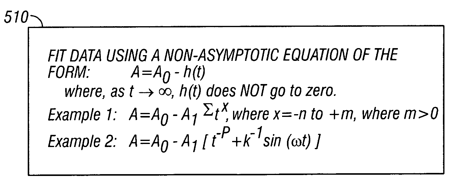
[0046]As shown in FIG. 5, in the present invention, a method and apparatus are provided that use a non-asymptotic curve to fit the data 510. In this embodiment, the method and apparatus fit a modified version of Eq. 1 to data, wherein the modified equation does not approach an asymptote at infinite time such as the examples shown in Equations 8 and 9 below, using the form A=A0−h(t) where t→∞ and h(t) does not go to zero.

A=A0−A1Σtx,where x=−n to +m, where m>0.  Eq. 8

A=A0−A1[t−p+k−1sin(ωt)].  Eq. 9

[0047]The sin(ωt) term can provide a better fit to data that has periodic spikes in response that commonly occur with every pump stroke as particulates are stirred up. Of course, this oscillating term prevents the curve from ever stabilizing to a fixed value no matter how long the time so it is not an asymptotic curve. The value of ω can be chosen to coincide with the pump-stroke frequency.

For Eq. 9, the present invention finds best A0, A1 using a linear least squares fit to the N data point...

third embodiment

[0048]As shown in FIG. 6, in a third embodiment, the present invention provides for a pattern recognition 610. As shown in FIG. 6, the present invention performs a pattern recognition for a trial-and-error estimate of A0, rather than a direct calculation of A0. In this embodiment, the pattern to be observed is the closest resemblance to a straight line as determined by the highest correlation coefficient, R, for a linear least squares fit. The method and apparatus performs a series of linear least squares fits to the absorbance data using a series of different estimates of A0 starting with, A+ε, A+2ε, up to A+Nε, where A+Nε0 value for which the fit is closest to a straight line in log-log space then becomes the best estimate of A0. Closeness of the fit to a straight-line shape is determined by the closeness of R2 to unity, where R2 is the correlation coefficient squared that ranges from 0 (no correlation) to 1 (perfect correlation). That is, for a series of A0 guesses, find the best...


PUM

PropertyMeasurementUnit
path lengthaaaaaaaaaa
timeaaaaaaaaaa
absorbanceaaaaaaaaaa

Abstract

The present invention provides method and apparatus for quantifying sample clean up in real time by providing curve-fitting measurements of optical or other physical properties of fluid downhole. Fluid is extracted from the formation surrounding a borehole. As fluid continues to be extracted the composition of the extracted fluid changes, altering the measured values of optical and physical properties of the fluid. Measurements are made of optical or physical properties of the sampled fluid, analysis is performed on the acquired measured data points.

Description

[0001]This application is a Continuation-In-Part of the U.S. patent application Ser. No. 11 / 112,626 filed on Apr. 22, 2005, now abandoned.BACKGROUND OF THE INVENTION[0002]1. Field of the Invention[0003]The invention relates generally to a method and apparatus for quantifying fluid contamination as an indication of sample cleanup in real time in a wellbore environment. Specifically, the invention is a method and apparatus for measurement of physical properties of fluid being pumped from a formation surrounding a wellbore by a wireline or monitoring while drilling tool to estimate sample cleanup or to predict the time at which a sample having a desired purity can be obtained.[0004]2. Summary of the Related Art[0005]In wellbore exploration, typically drilling muds such as oil-based muds and synthetic-based muds or water-based muds are used. The filtrates from these muds generally invade the formation through the borehole wall to an extent, meaning that this filtrate must be removed fro...

Claims


Application Information

Patent Timeline
Patent Type & Authority Patents(United States)
IPC IPC(8): G01N31/00
CPCE21B47/102G01V1/50E21B49/005G01N2035/00702E21B47/113E21B49/0875E21B47/114
Inventor DIFOGGIO, ROCCOPOHL, BERNARDO
Owner BAKER HUGHES INC
Why Eureka
Try Eureka