Combustion chamber intermediate part for a gas turbine

a gas turbine and combustion chamber technology, applied in the direction of machines/engines, efficient propulsion technologies, lighting and heating apparatus, etc., can solve the problems of increasing mechanical and thermal loads, reducing the overall efficiency of the turbine, and steep temperature rise in the individual combustion chambers, so as to achieve the effect of lowering the cooling requirements

Active Publication Date: 2007-11-27
SIEMENS ENERGY GLOBAL GMBH & CO KG
View PDF8 Cites 5 Cited by
  • Summary
  • Abstract
  • Description
  • Claims
  • Application Information

AI Technical Summary

Benefits of technology

[0006]On the basis of this prior art, the object of the invention is to create a gas turbine in which the thermal and mechanical loads of the individual combustion chambers are significantly reduced in the transition section so that cooling requirements can be lowered in this area.
[0008]Because deflection of the hot gas flow in the direction of the engine axis due to the embodiment of the transition section of the individual combustion chamber and the input area of the turbine chamber in accordance with the present invention no longer takes place almost entirely in the transition section of the individual combustion chamber but is substantially relocated to the input area of the turbine chamber, the turbine elements located in the input area of the turbine chamber, in particular the fixed blades, are exposed to the mechanical and thermal loads associated with the deflection. These elements, which are embodied as cast elements to withstand the thermal stresses already present, can dissipate the additional thermal loads resulting from the deflection of the gas flow much better however than the reshaped transition sections of the combustion chambers. Thanks to the essentially linear hot gas flow in the area of the transition section, these are relieved of thermal loads to such an extent that cooling requirements in this area can be significantly reduced. Compared with prior art, material stresses on the individual combustion chamber in the transition section are therefore reduced, which has a positive effect overall on the durability and service life of this component. The fact that there is no longer any need to expend a great deal of time, money and effort on cooling the transition section of the individual combustion chamber means that the chamber is easier to design and that designers have much greater freedom.
[0009]In a beneficial embodiment of the invention, the transition section of at least one individual combustion chamber has an internal wall located closer to a turbine shaft and an external wall located further away from the turbine shaft, whereby the internal and external walls of the individual combustion chamber are essentially straight or curve gently in the direction of the engine axis. A gentle curve in the direction of the engine axis means a curve with a large radius, with the hot gas flow being deflected in a wide arc, so that thermal load peaks can be avoided in these areas. With the internal and externals walls of the transition section running essentially in a straight line there are no additional thermal or mechanical loads due to the deflection of the gas flow.
[0011]In accordance with a further beneficial feature of the invention, fixed blades are arranged in the turbine chamber with fixed blade platforms aligned essentially parallel to the engine axis, with at least one fixed blade platform in the input area of the turbine chamber running at an angle in the direction of the combustion chamber longitudinal axis. In this way, the fixed blade platforms running at an angle or in a curve deflect the hot gas flow and absorb the additional thermal and mechanical loads resulting from deflection. Since the fixed blades are castings, as mentioned above, and as such have excellent thermal conductivity, additional thermal loads arising at this point because of the deflection of the hot gas flow can be easily dissipated and absorbed with comparatively simple cooling measures.
[0012]In accordance with a further beneficial embodiment of the invention, the fixed blade platforms in the input area can be lengthened in the direction of the individual combustion chambers to further relieve the load on the transition section of the individual combustion chamber. In this way the hot gas flow can hit the lengthened sections of the fixed blade platforms very early and be deflected in the direction of the engine axis by these elements. With such a fixed blade platform in the input area of the turbine chamber, lengthened in the direction of the individual combustion chamber the radius in which deflection of the hot gas flow takes place can also be increased and the thermal and mechanical loads arising from deflection can be distributed over a larger area.

Problems solved by technology

One problem with this procedure is that in the area of the baffles embodied with comparatively small radii the hot gas flow hits the walls of the individual combustion chambers in the input area, exposing them to increased mechanical and thermal loads.
This leads to a steep temperature rise in the individual combustion chambers in the transition section, which in turn calls for increased cooling.
The pressure drops required to cool such an embodied transition section of the individual combustion chambers and the quantities of additional cooling gas required reduce the overall efficiency of the turbine and are therefore seen as disadvantageous.
In addition, the cooling arrangement shown in U.S. Pat. No. 4,719,748 for the individual combustion chambers calls for higher design costs as the chambers have to be provided with a double-shell casing along their entire length.

Method used


Image

  • Combustion chamber intermediate part for a gas turbine
  • Combustion chamber intermediate part for a gas turbine

Examples


Embodiment Construction

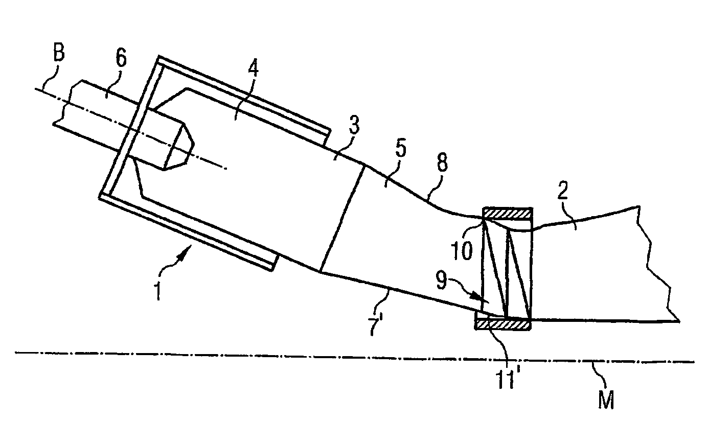
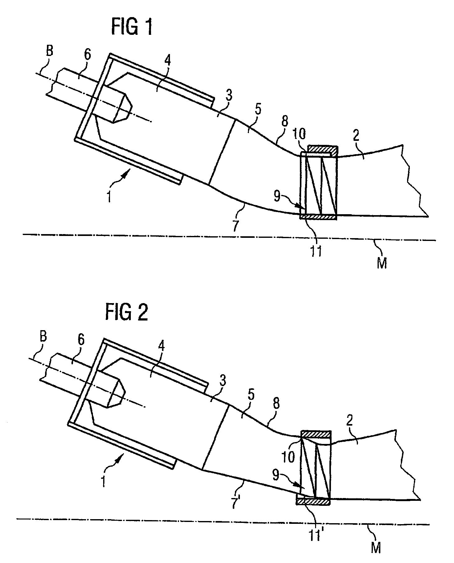
[0020]FIG. 1 shows a section of a turbine 1 in accordance with the invention in a first embodiment. In particular it shows an individual combustion chamber 3 in the transition to a turbine chamber 2 of the gas turbine 1. The individual combustion chamber 3 comprises an input section 4 and a transition section 5. The input section 4 is cylindrical with a circular base area; the transition section 5 changes the circular cross-section of the input section 4 in a cross-section with the form of a section of an annular segment. In the gas turbine 1 as per the invention there are a plurality of such individual combustion chambers 3 which on the output side of the transition sections 5 define an annular gap which leads to the turbine chamber 2.

[0021]Upstream of the individual combustion chamber 3 is a burner 6 which ignites a mixture of an oxygenated combustion gas and a fuel. Actual combustion then takes place in the individual combustion chambers 3 of the gas turbine 1, with resultant hot...


PUM


Abstract

This invention relates to a gas turbine having a combustion chamber arrangement and a turbine chamber connected downstream of said combustion chamber arrangement, wherein the combustion chamber arrangement includes a plurality of individual combustion chambers formed by input areas and transition areas converging in an annular gap leading to the turbine chamber and wherein the longitudinal axes of the individual combustion chambers are placed at an angle relative to an engine axis that is defined by the axial extension of the turbine chamber. In order to improve said gas turbine by visibly reducing the thermal and mechanical loads of the individual combustion chambers in the transition area so that cooling requirements can be lowered in said area, the transition area of at least one individual combustion chamber into the turbine chamber is deflected in the direction of the engine axis and substantially in the input area of the turbine chamber.

Description

CROSS REFERENCE TO RELATED APPLICATIONS[0001]This application is the U.S. National Stage of International Application No. PCT / EP02 / 09615, filed Aug. 28, 2002 and claims the benefit thereof. The International Application claims the benefits of European application No. 01121088.7 EP filed Sep. 3, 2001, both of the applications are incorporated by reference herein in their entirety.FIELD OF INVENTION[0002]The invention relates to a gas turbine with a combustion chamber arrangement and a turbine chamber connected downstream of this combustion chamber arrangement, wherein the combustion chamber arrangement includes a plurality of individual combustion chambers formed by input sections and transition sections converging in an annular gap leading to the turbine chamber and wherein the longitudinal axes of the individual combustion chambers are placed at an angle relative to an engine axis that is defined by the axial alignment of the turbine chamber.BACKGROUND OF INVENTION[0003]Such gas tu...

Claims


Application Information

Patent Timeline
Patent Type & Authority Patents(United States)
IPC IPC(8): F02C3/14F23R3/42F01D9/02
CPCF01D9/023Y02T50/675Y02T50/60
Inventor OLTMANNS, LEGAL REPRESENTATIVES, IRISTIEMANN, DECEASED, PETER
Owner SIEMENS ENERGY GLOBAL GMBH & CO KG
Why Eureka
Try Eureka