Rotary die module

a technology of die module and rotary die, which is applied in the direction of presses, stock shearing machines, manufacturing tools, etc., can solve the problems of lack of adaptability, time and effort, and limitations in prior art modules in adaptability to different die rolls,

Inactive Publication Date: 2007-11-27
COX WILLIAM A
View PDF23 Cites 29 Cited by
  • Summary
  • Abstract
  • Description
  • Claims
  • Application Information

AI Technical Summary

Benefits of technology

[0009]The inventive die module or frame includes a base having a plurality of columns removably mounted thereto in spaced relationship to one another. The columns extending from the base define a first axis of movement. The inventive module further includes at least one cross member that moveably engages the columns to position the cross member along the first axis of movement distant from the base. The module includes at least one first modular die support mounted to the base and at least one second modular die support mounted to the cross member each for rolling engagement with at least one rotary cutting die positioned between the base and the cross member. The modular die supports may easily be removed from the frame for replacement by different die supports to accommodate different die rolls for alternate applications.

Problems solved by technology

Prior design frames are typically welded or securely bolted together requiring significant time and effort to disassemble them to change or service the dies or frame.
Prior art modules are limited in their flexibility of adapting to different die rolls, die diameters and applications such as high versus low speed operations.
The lack of adaptability stems from machined steel frames, integration of the die supports with the frame, and reliance on bearing blocks to support and retain the die rolls in operation.
These removal, installation, and adjustment processes are time consuming resulting in significant down time of the die module.
Due to the costly steel frames and associated die rolls, it is cost prohibitive to have extra frames with installed alternate dies to reduce changing and readjusting the modules.
Due to the nature of the prior designs, prior frames were complex in design, expensive to manufacture and assemble and required extensive time to change and readjust the die rolls.

Method used


Image

  • Rotary die module
  • Rotary die module
  • Rotary die module

Examples


Embodiment Construction

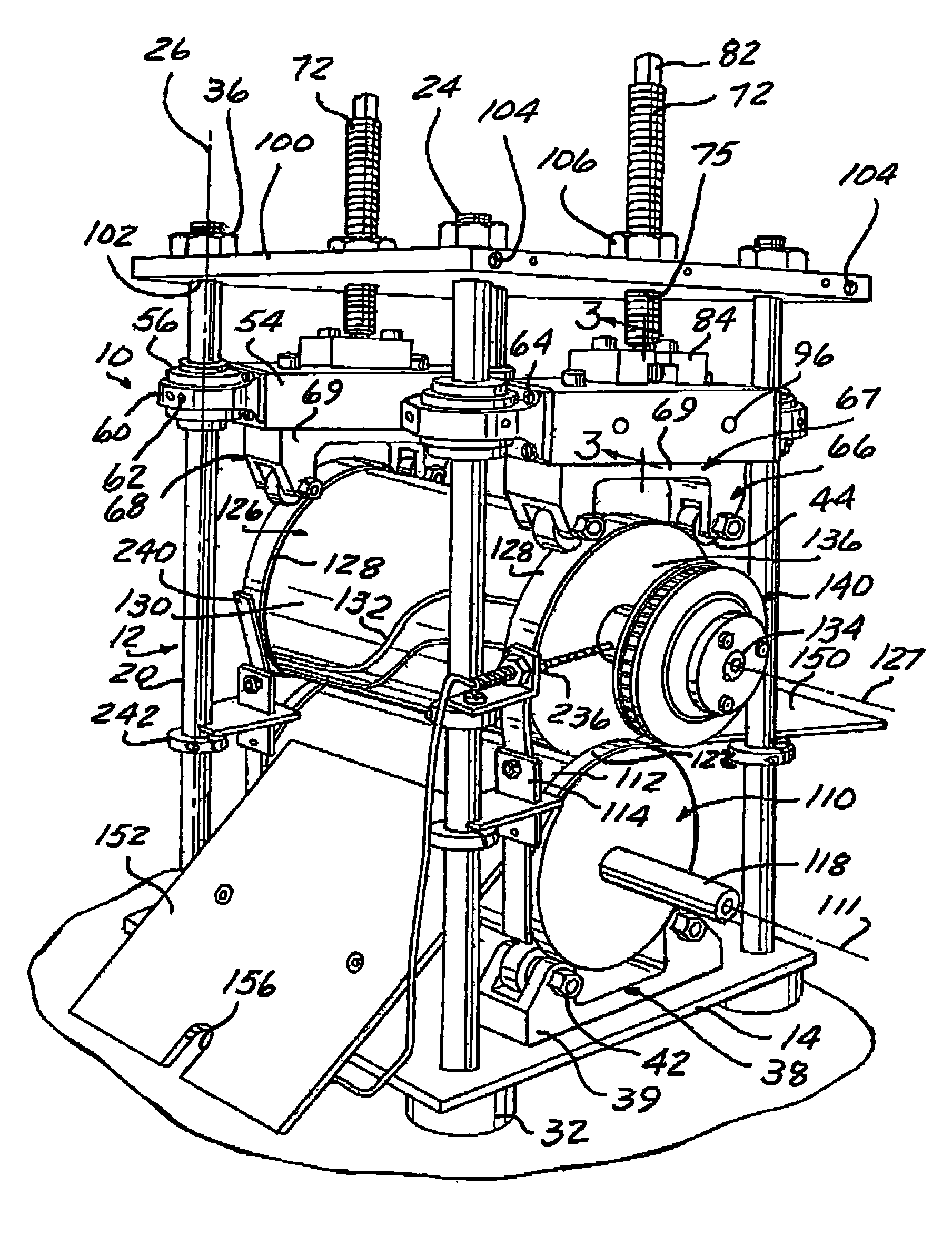
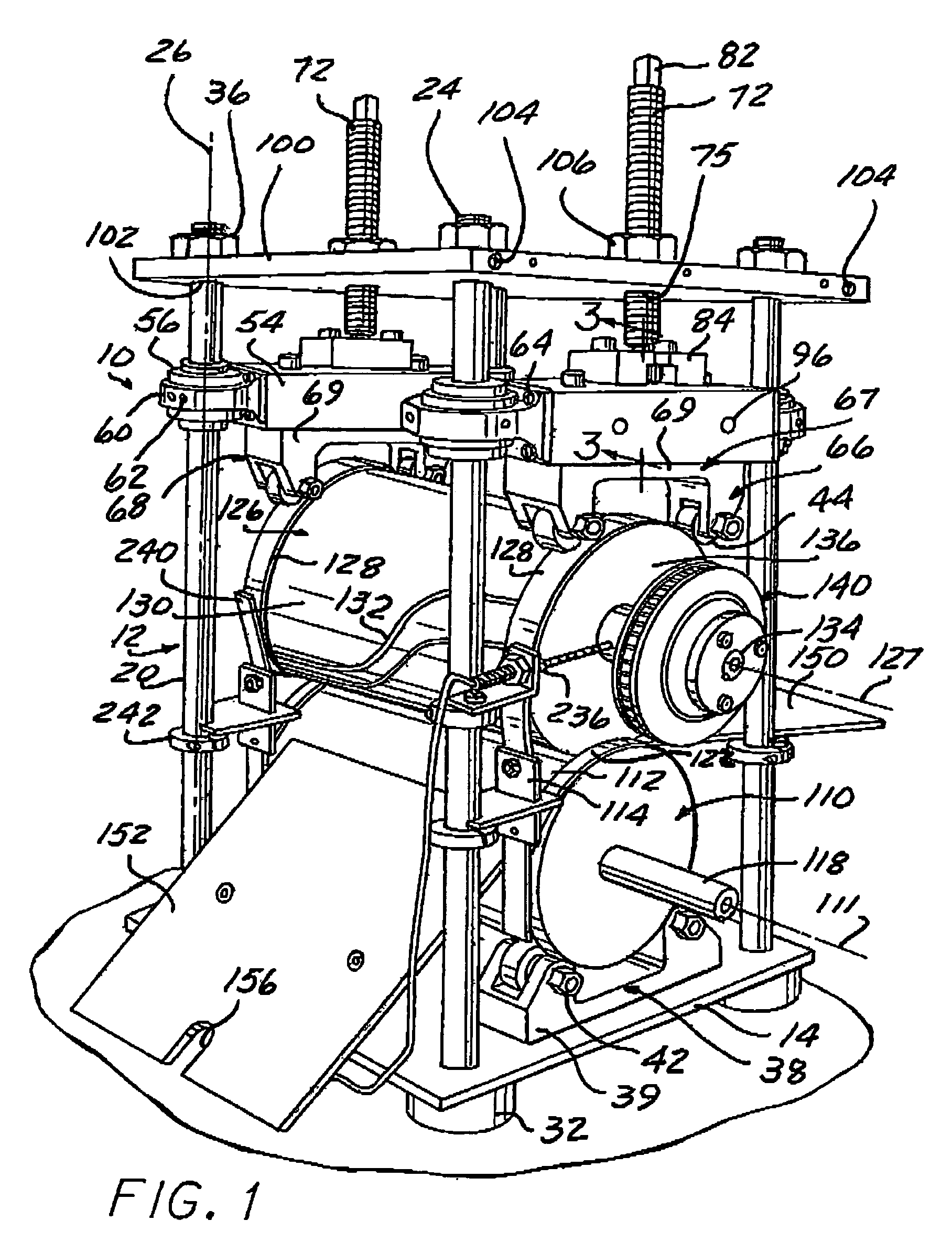
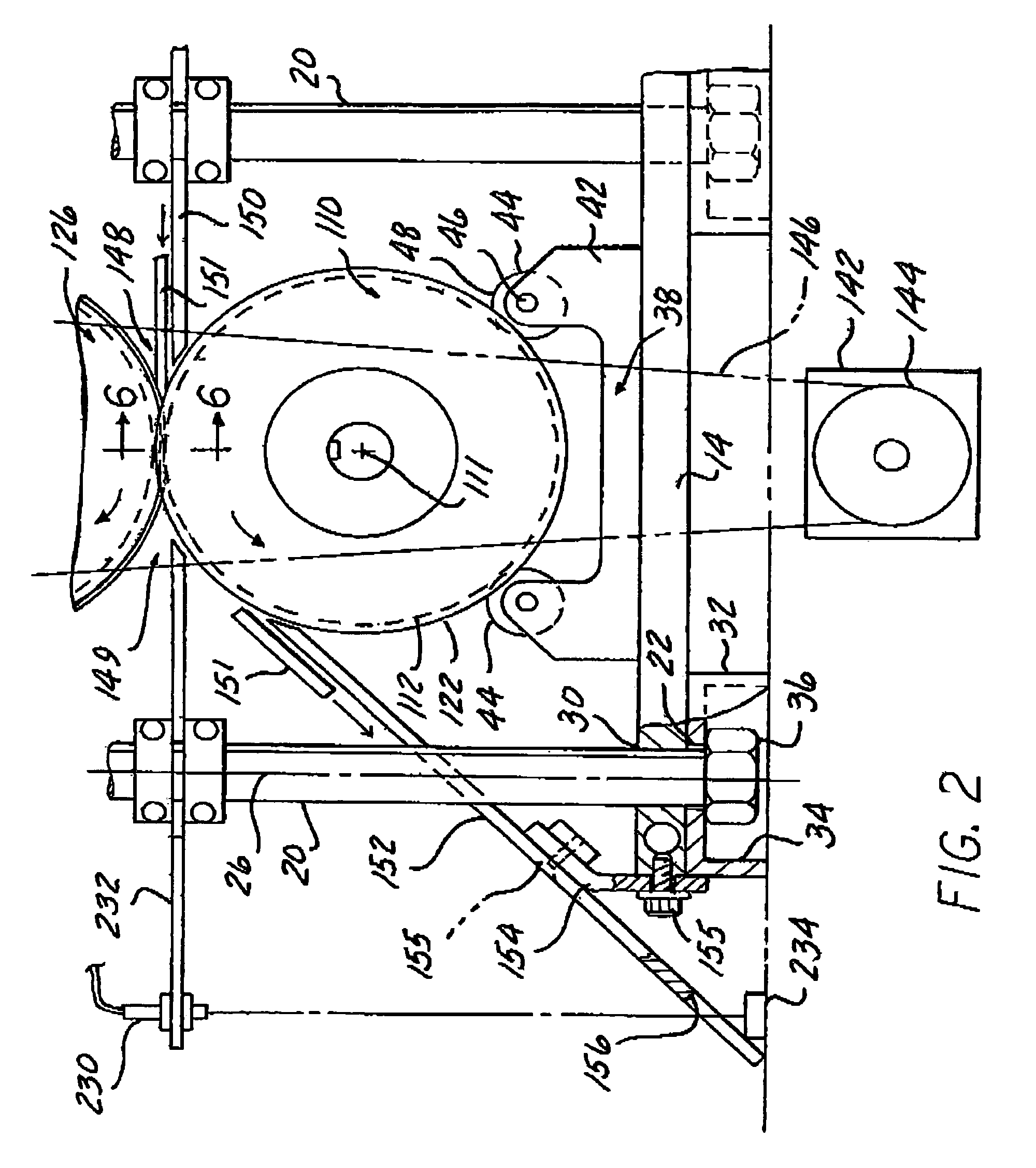
[0033]Referring to FIGS. 1 and 2, a rotary die module 10 is illustrated. Die module 10 includes a frame assembly 12 including a base 14, a plurality of columns 20, cross members 54, a first modular die support 38, a second modular die support 66, a first die roll 110, a second die roll 126, and a cover 100.

[0034]The base 14 is illustrated as a substantially rigid plate having a generally square shape. Base 14 includes base supports 32 positioned adjacent to the corners of base 14 to elevate frame assembly 12 above a working surface such as a table or floor to facilitate transporting the die module by hand or mechanical means such as a forklift or overhead hoist. Base 14 may consist of a ferrous or non-ferrous material such as steel, aluminum or other materials exhibiting similar strength and rigidity properties. Base supports 32 may be made from a similar material or, if a reduction in vibration is needed, a dampening material such as rubber or an elastomer. Although shown in a gene...


PUM

PropertyMeasurementUnit
90 degree anglesaaaaaaaaaa
speedaaaaaaaaaa
lengthaaaaaaaaaa

Abstract

A die apparatus for supporting and retaining rotary dies in operation having a base, a cover supported by a plurality of columns, a cross member moveable along the columns and modular die supports rollingly engaged with the rotary dies. A method of installing and removing the rotary dies from the apparatus includes moving the dies along a first axis of movement within the apparatus through use of a support strap and moving the dies to and from the apparatus through use of a conveyor.

Description

FIELD OF THE INVENTION[0001]The present invention relates to die cutting assemblies and more particularly to die module assemblies that support and retain rotary cutting dies. The invention further relates to methods of installing and removing the rotary cutting dies in die modules.BACKGROUND OF THE INVENTION[0002]With the advancement of high volume manufacturing of relatively thin, pliable materials, die cutting machines employing cylindrically-shaped rotary cutting dies have gained increased usage. Rotary die modules or frames which support and retain the cutting die rolls in operation typically consist of thick, rigid, machined steel bases, top plates and sidewalls. The sidewalls typically require a U-shaped vertical slot opening to the top of the sidewall and frame which are closed when the top plates are secured to the sidewalls. The sidewalls and slots are required to be machined to close tolerances to precisely locate bearing blocks on each end of the rolls to properly align ...

Claims


Application Information

Patent Timeline
Patent Type & Authority Patents(United States)
IPC IPC(8): B26D1/62B23D35/00B26D7/26
CPCB23D35/008B26D7/265B26D7/2628Y10T83/4833Y10T83/9372Y10T83/04Y10T83/4838Y10T83/483Y10T83/8748Y10T83/9464
Inventor COX, WILLIAM A.
Owner COX WILLIAM A
Why Eureka
Try Eureka