Electrical contact

a technology of electrical contact and support element, which is applied in the direction of coupling contact members, electrical connection bases, electrical apparatus, etc., can solve the problems of high material cost, cumbersome manufacturing of support elements, and high manufacturing cost of supporting elements, so as to reduce material expenditure for supporting elements and prevent damage to connectors and seals.

Active Publication Date: 2007-11-27
YAZAKI EURO
View PDF11 Cites 33 Cited by
  • Summary
  • Abstract
  • Description
  • Claims
  • Application Information

AI Technical Summary

Benefits of technology

[0008]The invention is based on the object, to provide an electrical contact with a two-part construction, i.e. with a contact element and a support element enclosing the contact element, for which the material expenditure for the support element is reduced and, furthermore, can be manufactured in a simple manner, wherein its elements, serving for the retainment in an accommodation chamber of a connector, are formed such, that damages on the connector and its seal are prevented.

Problems solved by technology

However, the support element is cumbersome to manufacture and necessitates because of the multi-layer construction, i.e. of the additional arrangement of the further wall, arranged above the upper wall, a relative large sheet metal portion, from which the support element is bent.
The manufacturing costs and also the costs for the material are correspondingly high.

Method used


Image

  • Electrical contact
  • Electrical contact
  • Electrical contact

Examples


Embodiment Construction

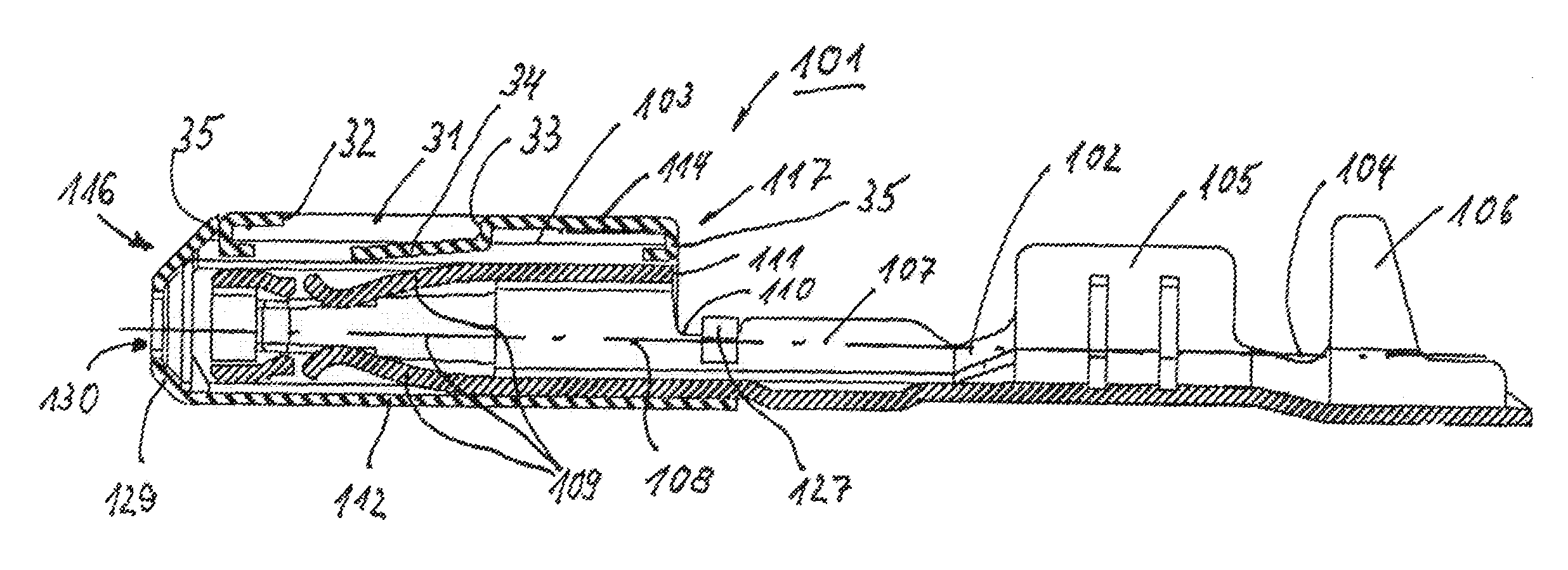
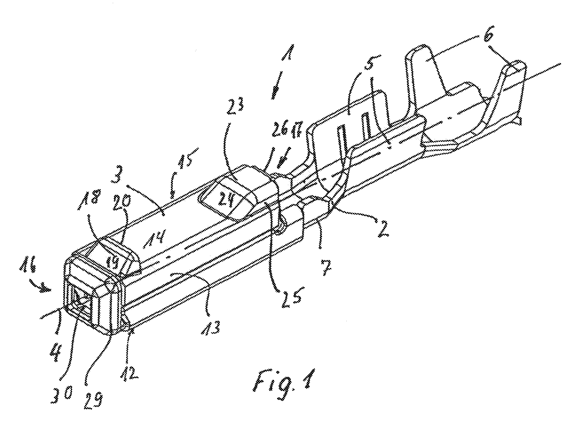
[0048]Following, in the description it is referred to FIGS. 1 to 5 as a whole concerning a first embodiment of a contact 1.

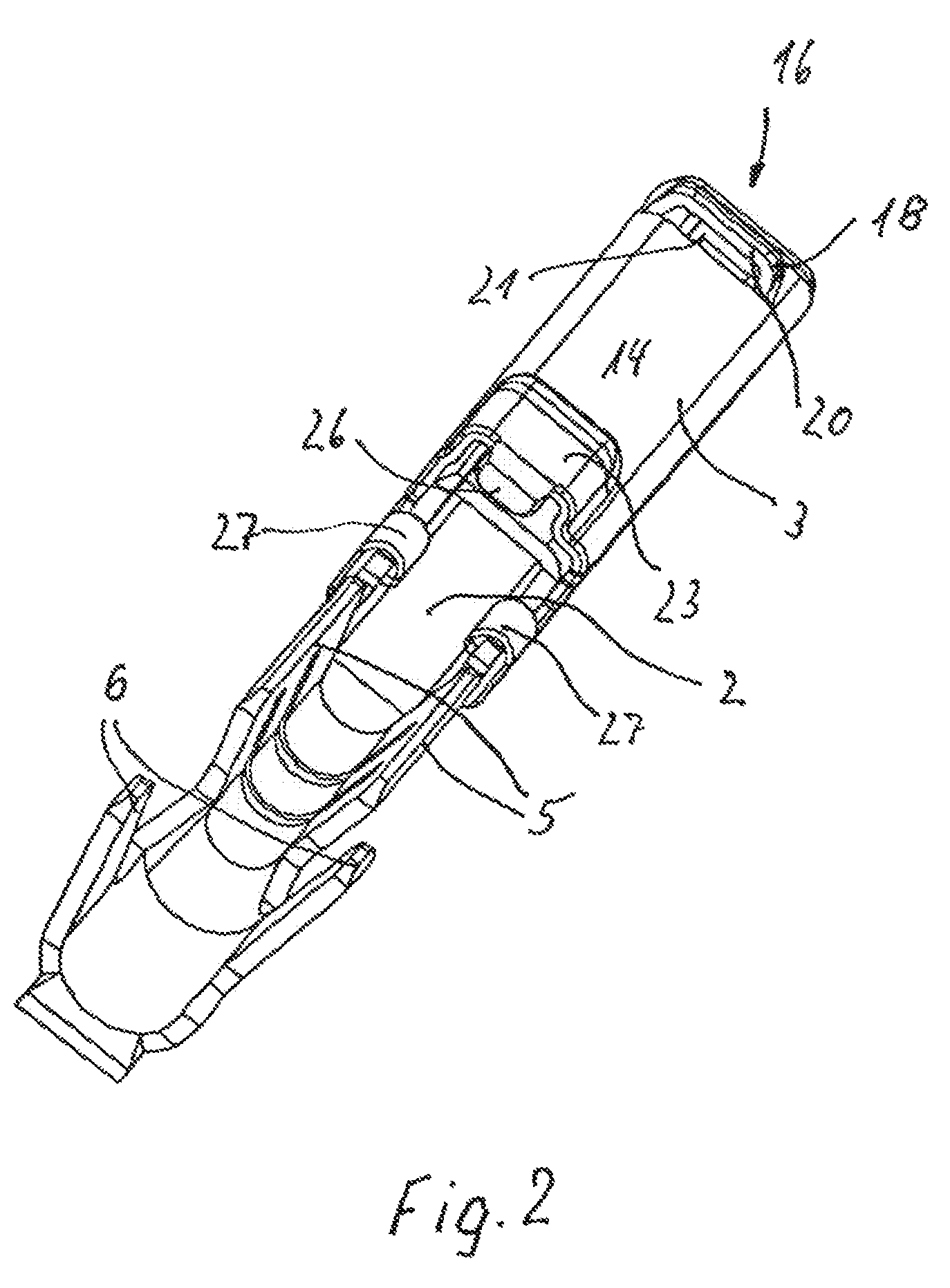
[0049]The contact 1 consists of the contact element 2 shown as an individual component in FIG. 5 and the support element 3 shown as an individual component in FIG. 4 and which encloses along the longitudinal axis 4 the contact element 2 on a partial length.

[0050]The contact element 2 is formed, starting from a sheet metal material having an electrical conductivity, by means of bending. It comprises a connection portion 5, formed by two first crimping tabs and serving for connecting an electrical conductor to the contact element 2 by means of crimping. Furthermore, two second crimping tabs 6 are provided to the right according to FIG. 5 on the connection portion 5 in form of first crimping tabs and two second crimping tabs 6 are offset to each other along the longitudinal axis 4 in such a way, that they are arranged one after the other after the crimping to the i...


PUM


Abstract

Electrical contact comprising a contact element, which has a connection portion, which serves for the electrical conducting connection to an electrical conductor, but a contact holding portion connected integrally to the connection portion, for contacting a counter contact, and a support element, which encloses the contact holding portion at least at a portion of its length along a longitudinal axis and formed in cross-section as a hollow rectangle delimited by four walls, has along the longitudinal axis a front end and a rear end facing the connection ports. Further, the support element has along the longitudinal axis (4) a front end (16) and a rear end (17), with the rear end (17) facing the connection portion (5), has a first projection (18) close to the front end (16), which first projection (18) has a first insertion portion (19) which distance from the longitudinal axis (4) increases in a direction from the front end (16) towards the rear end (17) and has side walls (22) and ends with an end edge (20), has a second projection (23) close to the rear end (17), which second projection (23) has a second insertion portion (24), which distance to the longitudinal axis (4) increases in a direction towards the rear end (17) in an inclined manner away from the first projection (18) relative to the longitudinal axis (4), wherein the first projection (18) as well as the second projection (23) are formed by non-cutting working from one of the walls (12, 13, 14, 15), so that they project away from the longitudinal axis (4) from that wall (14).

Description

BACKGROUND OF THE INVENTION[0001]The invention relates to an electrical contact with a contact element, which has integrally a connection portion and a contact holding portion, wherein the contact holding portion serves to be connected to a mating contact. The connection portion serves to connect for example by means of crimping an electrical conductor in an electrically conducting manner and if necessary additionally to produce a holding connection to the insulation of the cable having the conductor. The contact element is enclosed at its portion having the contact holding portion at least partially by a support element, which is also called cantilever spring and is, for example, made from a material, which has a higher strength than the contact element itself, i.e. from a steel. Such a support element is commonly made by starting from a sheet metal, i.e. by means of bending and punching as well as material connection of the butt joints by means of point welding or producing weldin...

Claims


Application Information

Patent Timeline
Patent Type & Authority Patents(United States)
IPC IPC(8): H01R11/22
CPCH01R4/185H01R13/187H01R13/432H01R13/4223H01R13/114H01R13/521
Inventor LUTSCH, HARALD MICHAELBUDEN, VLADIMIRJAKOPLIC, IVICAAINCERI, RACHID
Owner YAZAKI EURO
Why Eureka
Try Eureka