Multiple frequency inductive resistivity device

Inactive Publication Date: 2007-11-27
SCHLUMBERGER TECH CORP
View PDF42 Cites 44 Cited by
  • Summary
  • Abstract
  • Description
  • Claims
  • Application Information

AI Technical Summary

Problems solved by technology

Another problem the industry has sought to address has been invasion of the formation by drilling mud.

Method used


Image

  • Multiple frequency inductive resistivity device
  • Multiple frequency inductive resistivity device
  • Multiple frequency inductive resistivity device

Examples


Embodiment Construction

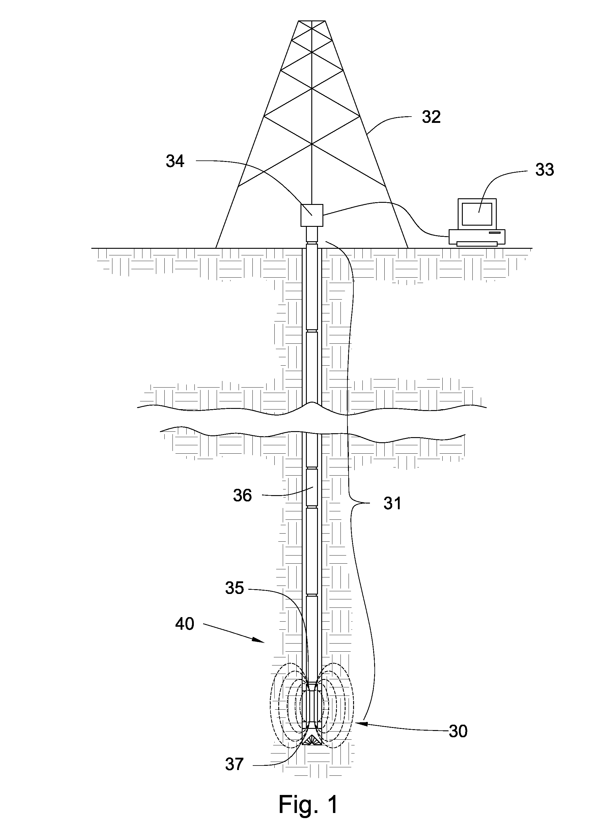
[0027]Referring now to FIG. 1, a downhole tool string 31 may be suspended by a derrick 32. The tool string may comprise one or more downhole components 36, linked together in a tool string 31 and in communication with surface equipment 33 through a downhole network. Having a network in the tool string 31 may enable high-speed communication between each device connected to it and facilitate the transmission and receipt of data between sensors, energy sources, and energy receivers.

[0028]The tool string 31 or surface equipment 33 may comprise an energy source or multiple energy sources. The energy source may transmit electrical current to one or more downhole components 36 on the bottom hole assembly 37 or along the tool string 31. In some embodiments of the invention, one or more downhole component 36 may comprise sensors. These sensors may sense gamma rays, radioactive energy, resistivity, torque, pressure, or other drilling dynamics measurements or combinations thereof from the form...


PUM

PropertyMeasurementUnit
induction resistivityaaaaaaaaaa
electrical currentaaaaaaaaaa
frequencyaaaaaaaaaa

Abstract

In one aspect of the present invention, an induction resistivity tool incorporated into a downhole tool string component comprises an annular radial recess disposed along an outside surface of a tubular wall of the downhole component. At least one electrically insulated induction coil is disposed in the radial recess and adapted to transceive induction signals outward from the tubular wall when carrying an electrical current. The at least one coil is tuned for an optimal signal frequency and an actuator in the downhole component is adapted to put an electrically conductive element into and out of electrical contact with the at least one coil and thereby change the optimal signal frequency.

Description

CROSS REFERENCE TO RELATED APPLICATIONS[0001]This application is a continuation-in-part of U.S. patent application Ser. No. 11 / 676,494 filed on Feb. 19, 2007 now U.S. Pat. No. 7,265,649 and entitled Flexible Inductive Resistivity Device. U.S. patent application Ser. No. 11 / 676,494 is herein incorporated by reference for all that it contains.BACKGROUND OF THE INVENTION[0002]The present invention relates to the field of downhole oil, gas, and / or geothermal exploration and more particularly to the field of resistivity tools for tool strings employed in such exploration.[0003]For the past several decades, engineers have worked to develop apparatus and methods to effectively obtain information about downhole formations, especially during the process of drilling. Logging-while-drilling (LWD) refers to a set of processes commonly used by the industry to obtain information about a formation during the drilling process in order to transmit the information from components located downhole on ...

Claims


Application Information

Patent Timeline
Patent Type & Authority Patents(United States)
IPC IPC(8): H01F27/29
CPCE21B47/01H04B5/0043H01Q1/04H01F27/365H01F38/14H01F27/36H01F27/366
Inventor HALLTURNER, PAULASHUMWAY, JIMWILDE, TYSON J.MILLS, JAD A.
Owner SCHLUMBERGER TECH CORP
Why Eureka
Try Eureka