Electro-optic vision systems

Inactive Publication Date: 2007-11-27
GEOVECTOR
View PDF28 Cites 188 Cited by
  • Summary
  • Abstract
  • Description
  • Claims
  • Application Information

AI Technical Summary

Problems solved by technology

For example, a user of a city road map may not be able to see a tunnel on Elm Street if the user is currently seven miles away on First Street and looking in the direction of the Elm Street tunnel.
Unfortunately, it is not always possible to translate the information from a map to the real scene that the information represents as the scene is actually viewed.
This may result in the condition of an “upside down” map that is quite difficult to read (the case when the user is traveling south).
Although translating the directions of the map to reality is a formidable task, it is an even greater problem to translate the symbols on the map to those objects in reality which they represent.
The fact that the appearance of the tunnel from infinitely many points of view is prohibitively difficult to represent on a map accounts for the use of a simple symbol.
Furthermore, the map does not have any indication from which point of view the user will first see the tunnel, nor any indication of the path which the user will take to approach the tunnel.
The computer generated map

Method used


Image

  • Electro-optic vision systems
  • Electro-optic vision systems
  • Electro-optic vision systems

Examples


Embodiment Construction

[0017]The present invention comprises a novel electro-optic system and associated image processing devices. The following description is presented to enable any person skilled in the art to make and use the invention. Descriptions of specific applications are provided only as examples. Various modifications to the preferred embodiments will be readily apparent to those skilled in the art, and the general principles defined herein may be applied to other embodiments and applications without departing from the spirit and scope of the invention. Thus, the present invention is not intended to be limited to the embodiments shown, but is to be accorded the widest scope consistent with the principles and features disclosed herein.

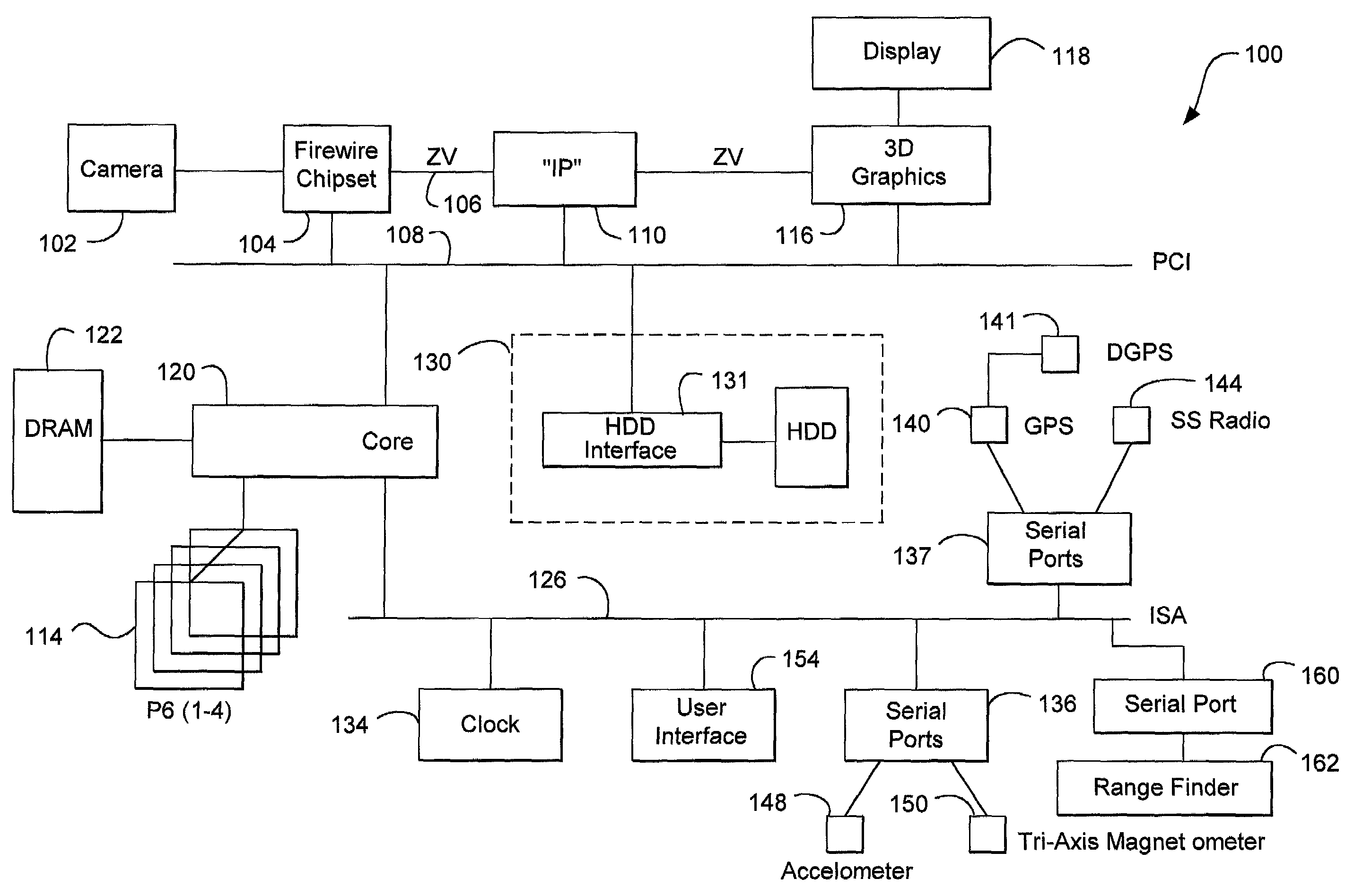
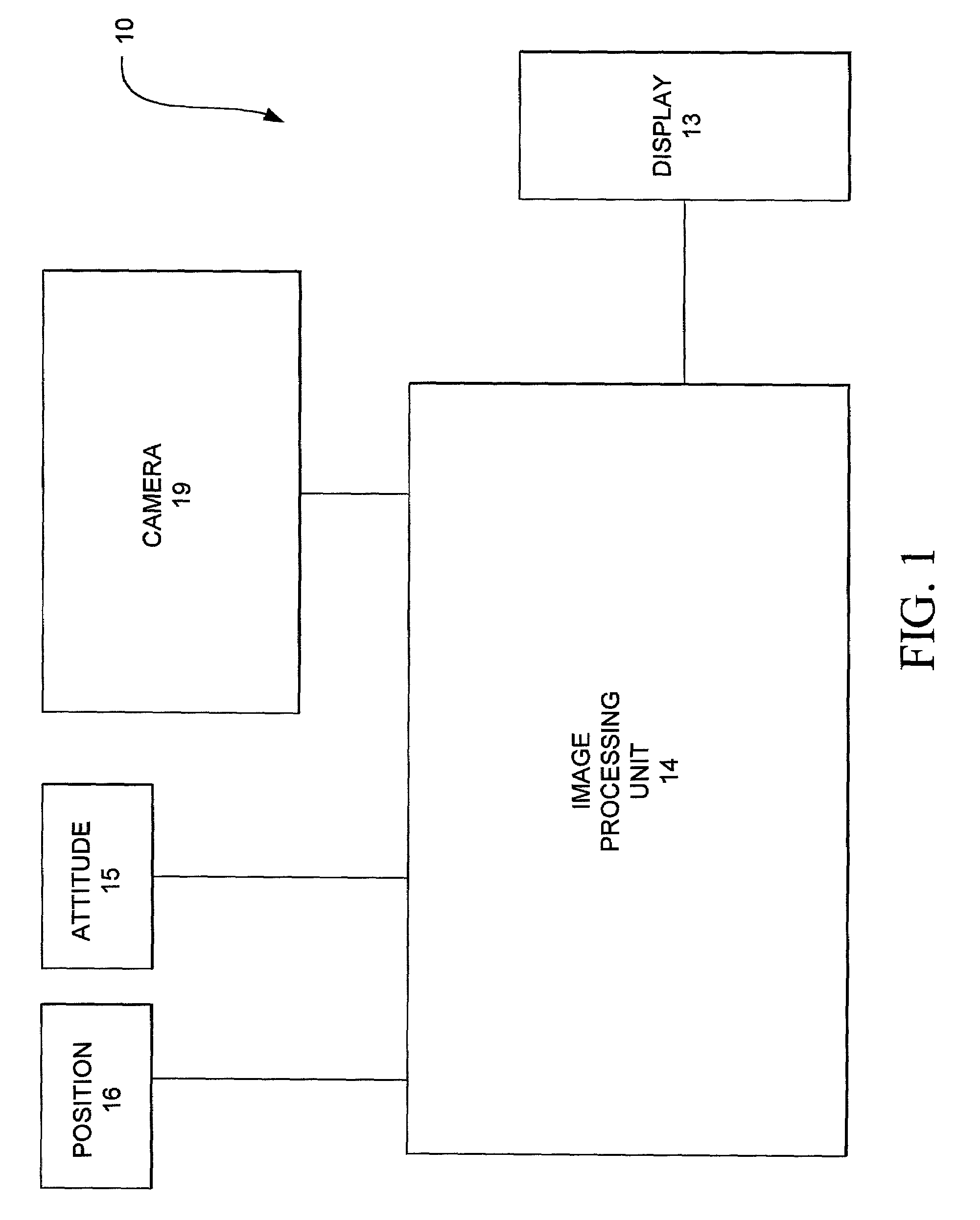
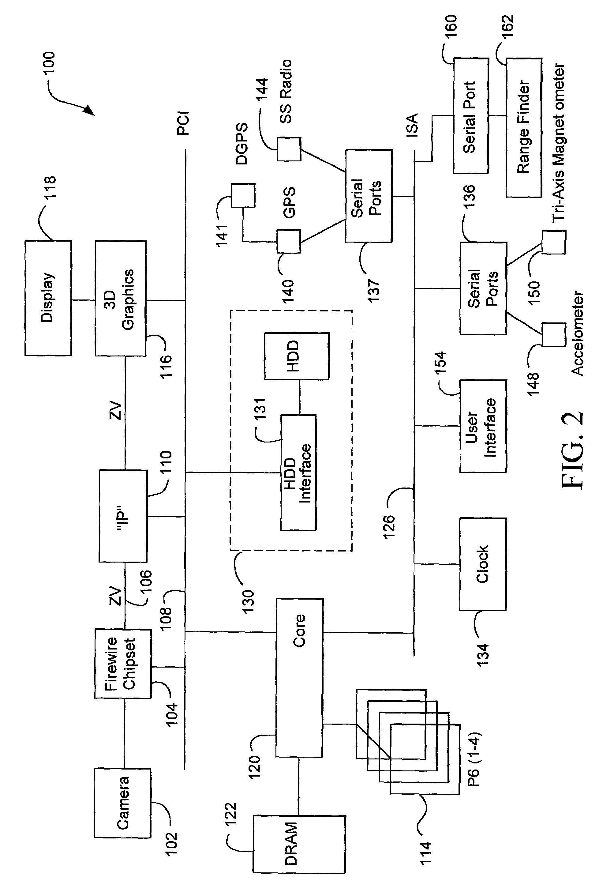
[0018]FIG. 1 is a block diagram of an electro-optic system 10 of the present invention. System 10 comprises a position determining means 16, an attitude determining means 15, a camera 19, an image processing unit 14, and a display 13. Camera 19 comprises an electr...


PUM


Abstract

An image processing system for delivering real scene information to a data processor. The system includes the data processor, an image-delivery mechanism, an information delivery mechanism, and a graphic processor.

Description

CROSS-REFERENCES TO RELATED PATENT APPLICATIONS[0001]This application is a continuation-in-part of the following patent applications: Ser. No. 08 / 691,784, filed Aug. 2, 1996; now U.S. Pat. No. 6,064,398 Ser. No. 08 / 119,360, filed on Sep. 10, 1993 now U.S. Pat. No. 5,815,411; Ser. No. 08 / 307,360, filed on Sep. 14, 1994 now U.S. Pat. No. 5,742,521; Ser. No. 08 / 335,912, filed on Nov. 8, 1994 now U.S. Pat. No. 5,682,332, Ser. No. 08 / 335,940, filed on Nov. 8, 1994 now U.S. Pat. No. 5,625,765; Ser. No. 08 / 335,710, filed on Nov. 10, 1994 now U.S. Pat. No. 5,619,078; Ser. No. 08 / 441,299, filed on May, 15, 1995 now U.S. Pat. No. 5,530,102; Ser. No. 08 / 480,689, filed on Jun. 7, 1995 now abandoned; Ser. No. 08 / 482,943, filed on Jun. 7, 1995 now abandoned; and Ser. No. 08 / 571,096, filed on Dec. 12, 1995 now abandoned.FIELD OF THE INVENTION[0002]The present invention is generally related to electronic vision devices and methods, and is specifically related to image augmentation in combination wi...

Claims


Application Information

Patent Timeline
IPC IPC(8): G06T15/00G01C17/34G01C21/20G06T3/40G06T15/10
CPCG01C17/34G01C21/20G06T19/006G06T1/20G06T15/10G05B2219/32014
Inventor ELLENBY, JOHNELLENBY, THOMAS WILLIAMELLENBY, PETER MALCOLMMCGUIRE, KENYON E. B.
Owner GEOVECTOR
Why Eureka
Try Eureka