Routing method, node, packet communication system, program, and recording medium

a routing method and packet communication technology, applied in the field of routing methods, nodes, packet communication systems, programs, and recording media, can solve the problems of link layer headers and link band oppression, and achieve the effects of reducing processing load, reducing the total number of packets transmitted, and reducing the number of references to the routing tabl

Inactive Publication Date: 2007-11-27
NTT DOCOMO INC
View PDF11 Cites 11 Cited by
  • Summary
  • Abstract
  • Description
  • Claims
  • Application Information

AI Technical Summary

Benefits of technology

[0004]An object of the present invention is, therefore, to provide routing methods, nodes, packet communication systems, programs, and recording media succeeding in reducing the amount of communication data and achieving efficient utilization of network resources.
[0047]According to the present invention, when a plurality of packets have a common route at least in part of their routes to respective terminal addresses, information pieces of the packets are aggregated to reconfigure one aggregate packet, which can decrease the total number of packets transmitted on the network. The decrease in the total number of packets makes it feasible to decrease the number of references to the routing table, reduce the processing load, and increase the processing speed. As a result, it becomes feasible to achieve the efficient utilization of the network resources.

Problems solved by technology

In the above conventional technology, however, a number of equal data are transmitted toward the same node on a certain link, which poses a problem that the link band is oppressed by link layer headers.
The oppression of the link band is also caused by the transmission without data compression of packets.

Method used


Image

  • Routing method, node, packet communication system, program, and recording medium
  • Routing method, node, packet communication system, program, and recording medium
  • Routing method, node, packet communication system, program, and recording medium

Examples


first embodiment

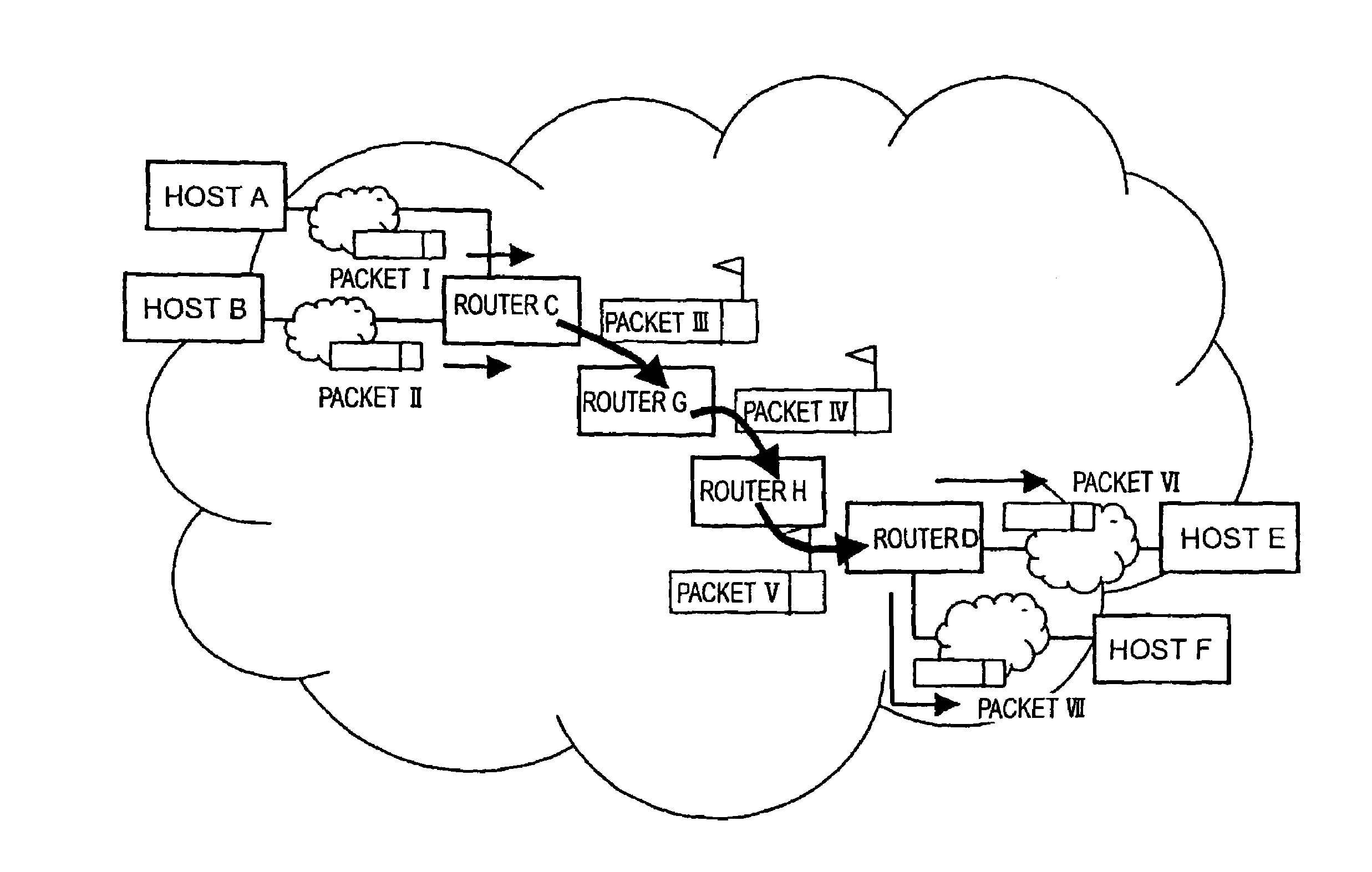
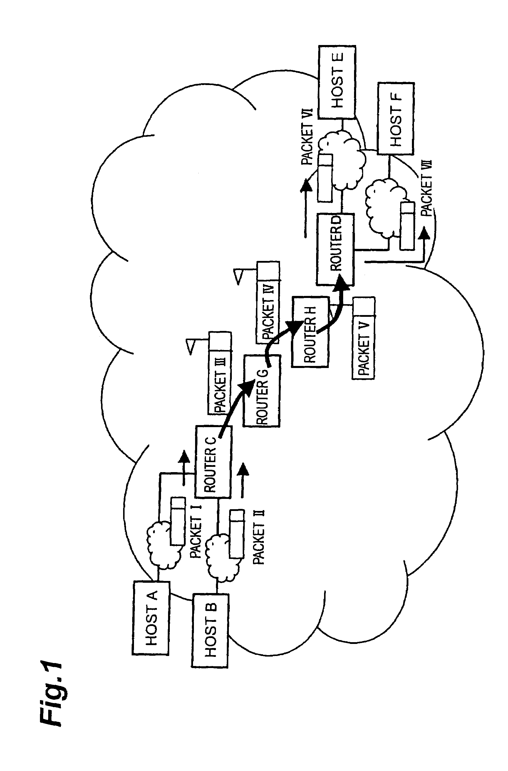
[0068]FIG. 1 is a diagram schematically showing a packet communication system as a first embodiment of the present invention. The nodes in the first embodiment are configured to capsule two or more IP packets together under an IP header to create an aggregate packet. The system herein is constructed on the premise that routing protocols such as OSPF (Open Shortest Path First) and others are active on the network. In FIG. 1, all the routers in the network have a restoring function of restoring an aggregate packet to a plurality of original packets. For example, they are routers C, D, G, and H in FIG. 1. The routers C and H also have an IP capsuling function, i.e., a packet aggregating function of aggregating two or more packets to create one aggregate packet, in addition to the restoring function. The routers G and D having only the restoring function are configured to execute the restoring flow shown in FIG. 4, for each of received packets. The routers C and H having the restoring f...

second embodiment

[0114]FIG. 13 is a diagram schematically showing a packet communication system as a second embodiment of the present invention. In the second embodiment, two or more IP packets are capsuled together under one IP header to create an aggregate packet. The system is configured on the premise that the routing protocols such as OSPF and others are active on the network and that the routers having the aggregating function preliminarily know the network topology and which node has the restoring function. It is also possible to manually set the network topology and the nodes with the restoring function, for each of the routers having the aggregating function. The router G in the network has neither the restoring function nor the aggregating function. The router H has only the restoring function by decapsuling. The router C and the router D have both the aggregating function by capsuling and the restoring function by decapsuling. Here the aggregating function is a function of executing the p...

third embodiment

[0129]FIG. 18 is a diagram schematically showing a packet communication system as a third embodiment. of the present invention. In the above-described first embodiment and second embodiment, the aggregate IP packet was created by capsuling of two IP packets, but it is also possible to create an aggregate Ethernet (registered trademark) frame from two IP packets without use of the capsuling technology. In the third embodiment, an aggregate Ethernet frame is created from two IP packets. The system is based on the premise that the routing protocols are used on the network, as in the conventional Internet.

[0130]Here the routers A and B have the aggregating function of an Ethernet level and all the routers on the network have the restoring function. The aggregating function of the Ethernet level herein is a function of executing the processing shown in the flowchart of FIG. 19. The restoring function of the Ethernet level is a function of identifying an aggregate flag of an aggregate Eth...


PUM


Abstract

A configuration comprises a destination address extracting / rewriting device 4 for extracting a destination address of a packet; a common-route packet extracting device 8 for extracting two or more packets having a common route at least in part of routes to their respective terminals from a plurality of packets, based on their extracted destination addresses; an aggregate packet creating device 9 for aggregating the plurality of packets having the common route at least in part of the routes to create an aggregate packet including information of each of the packets; a destination address giving device 10 for giving the aggregate packet a destination address so that the destination address of the aggregate packet is an address of an adjacent node on the common route; and an aggregate packet routing device 11 for routing the aggregate packet, based on the destination address.

Description

TECHNICAL FIELD[0001]The present invention relates to routing methods, nodes, packet communication systems, programs, and recording media improved in utilization efficiency of network resources in networks using the packet switching system.BACKGROUND ART[0002]In the conventional technology, even in the case where a plurality of packets with a destination of a common node and with equal data continuously arrive at a node performing routing, the packets are processed independently of each other. Namely, the node performing routing specifies the destination node with reference to header information of all the arriving packets and performs the routing of each packet toward the destination.DISCLOSURE OF THE INVENTION[0003]In the above conventional technology, however, a number of equal data are transmitted toward the same node on a certain link, which poses a problem that the link band is oppressed by link layer headers. The oppression of the link band is also caused by the transmission ...

Claims


Application Information

Patent Timeline
Patent Type & Authority Patents(United States)
IPC IPC(8): H04L12/28H04J3/24H04L12/56H04L45/74H04L47/41H04L47/43
CPCH04L29/06H04L45/00H04L69/04H04L49/90H04L69/22H04L2212/0025H04L2212/00H04L12/28H04L9/40
Inventor OMAE, KOJIIKEDA, TAKEHIROOKAJIMA, ICHIROUMEDA, NARUMI
Owner NTT DOCOMO INC
Why Eureka
Try Eureka