Method and apparatus for aerodynamic/hydrodynamic testing of a model

a technology of aerodynamic/hydrodynamic testing and model, applied in the direction of instruments, structural/machine measurement, vessel construction, etc., can solve the problems of affecting other measurements, affecting the flow, and unsatisfactory waves, etc., to improve aerodynamic and hydrodynamic testing

Inactive Publication Date: 2007-12-04
NAT RES COUNCIL OF CANADA
View PDF10 Cites 5 Cited by
  • Summary
  • Abstract
  • Description
  • Claims
  • Application Information

AI Technical Summary

Benefits of technology

[0011]It is an object of the present invention to obviate or mitigate the disadvantages of previously known methods and apparatuses for aerodynamic and hydrodynamic testing. It is a particular object to provide a method and apparatus that permits improved aerodynamic and hydrodynamic testing at low Reynolds numbers. In a first aspect, there is provided an apparatus for aerodynamic or hydrodynamic testing of a model. The apparatus comprises an enclosure for filling with a liquid, such as glycerine, of known properties, such as viscosity and density. The liquid can be a mixture of two or more liquids, such as water and glycerine. If liquid mixtures are used, a mixing unit can be provided that also controls the mixing ratio. The enclosure is covered such that the liquid is in full contact with all walls of the enclosure, thereby preventing the existence of a free surface. A mechanism is provided to impart movement to the model.
[0012]In a presently preferred embodiment of the apparatus of the present invention, the carriage that imparts the model motion is located above the enclosure. The enclosure's upper surface roof features a slit to allow passage of the model support strut. A seal installed along the full length of the slit ensures that the slit is normally closed yet it allows the motion of the strut by tightly surrounding it. This arrangement prevents the existence of a free surface in the vicinity of the strut as the model is pushed through the test medium. While it is contemplated that the seal can comprise a single inflatable member, it is presently preferred that the seal be formed by two cooperating inflatable seals arranged in face-to-face relation. To facilitate the displacement of air from within the enclosure by the liquid, the upper surface of the enclosure can be upwardly angled, to direct the liquid towards the seal, which for the purpose of filling the tank is opened, thus preventing the entrapment of air within the enclosure. In a further embodiment, the apparatus can include a track inside the enclosure to move the model, thereby obviating the need for a seal.

Problems solved by technology

The free surface, present in both water tunnels and towing tanks, causes undesirable waves, turbulence, and other disturbances in the surface of the medium.
These disturbances can cause changes in the pressure distribution within the tank, thereby altering the flow and affecting other measurements.
External factors, such as vibration due to vehicular traffic, as well as the movement of the model itself, can also adversely affect the conditions in a tank or tunnel with a free surface.
However, once the channel is closed, there is no mechanism to impart movement to the submerged model, and free surfaces may still be present.
The disadvantages of conventional wind and water aerodynamic testing apparatus become even more apparent when it is desired to test at low Reynolds number flows.
The experimental determination of airloads at low Reynolds number flows is extremely difficult with conventional apparatus, because the generated loads are so low as to be virtually immeasurable with an acceptable accuracy.
Furthermore, the small size of the models required to carry out the tests, and correspondingly small associated flow features, seriously limits the accuracy and resolution with which the flow surrounding the test vehicle can be investigated.
In addition, the rapid rate of growth of boundary layers at low Reynolds number conditions precludes the use of a test facility where the fluid moves with respect to the surrounding walls, as in the case of a wind or water tunnel, because the wall boundary layers prevent the development of a suitable velocity profile in the test section.

Method used


Image

  • Method and apparatus for aerodynamic/hydrodynamic testing of a model
  • Method and apparatus for aerodynamic/hydrodynamic testing of a model
  • Method and apparatus for aerodynamic/hydrodynamic testing of a model

Examples


Embodiment Construction

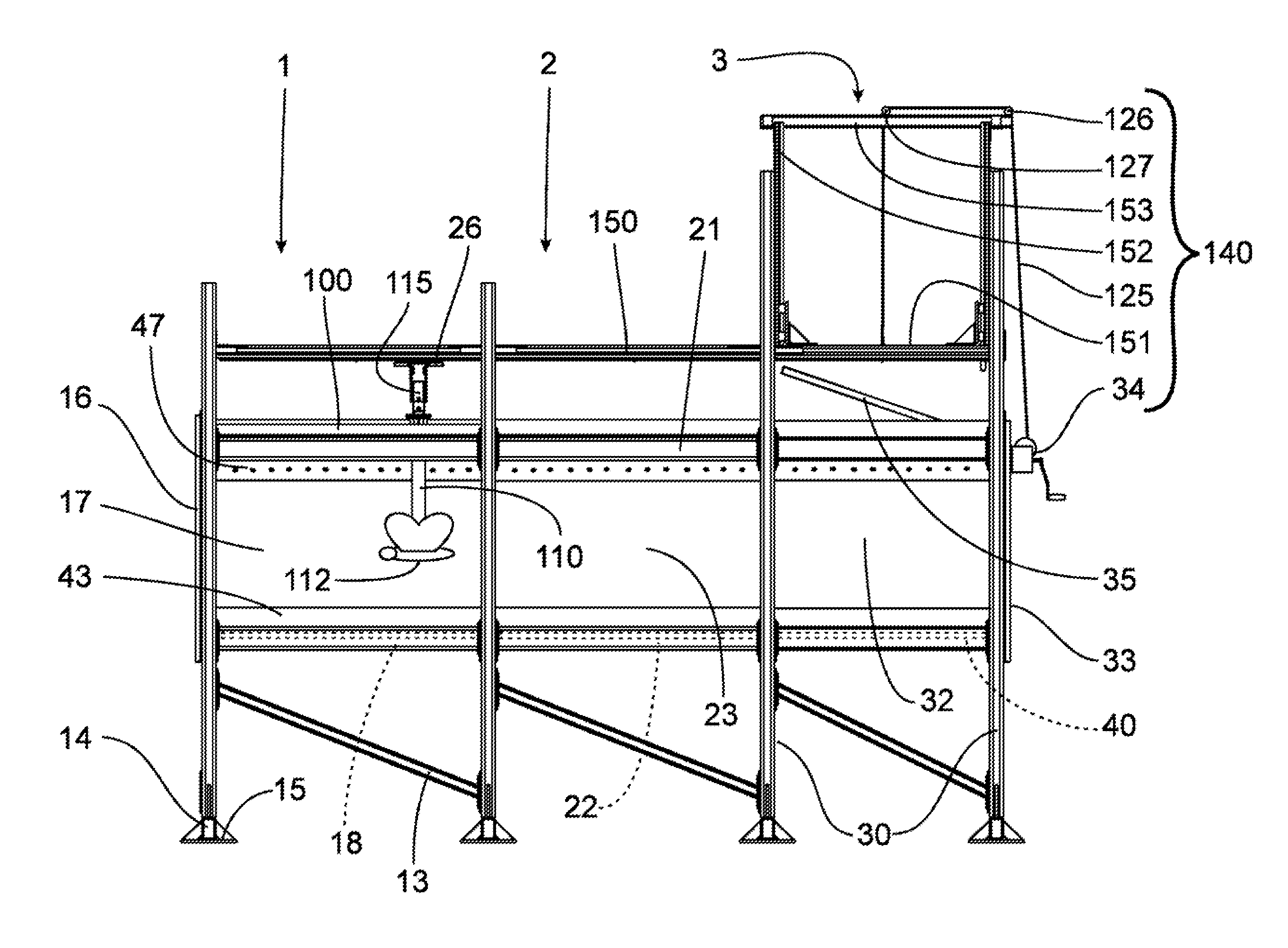
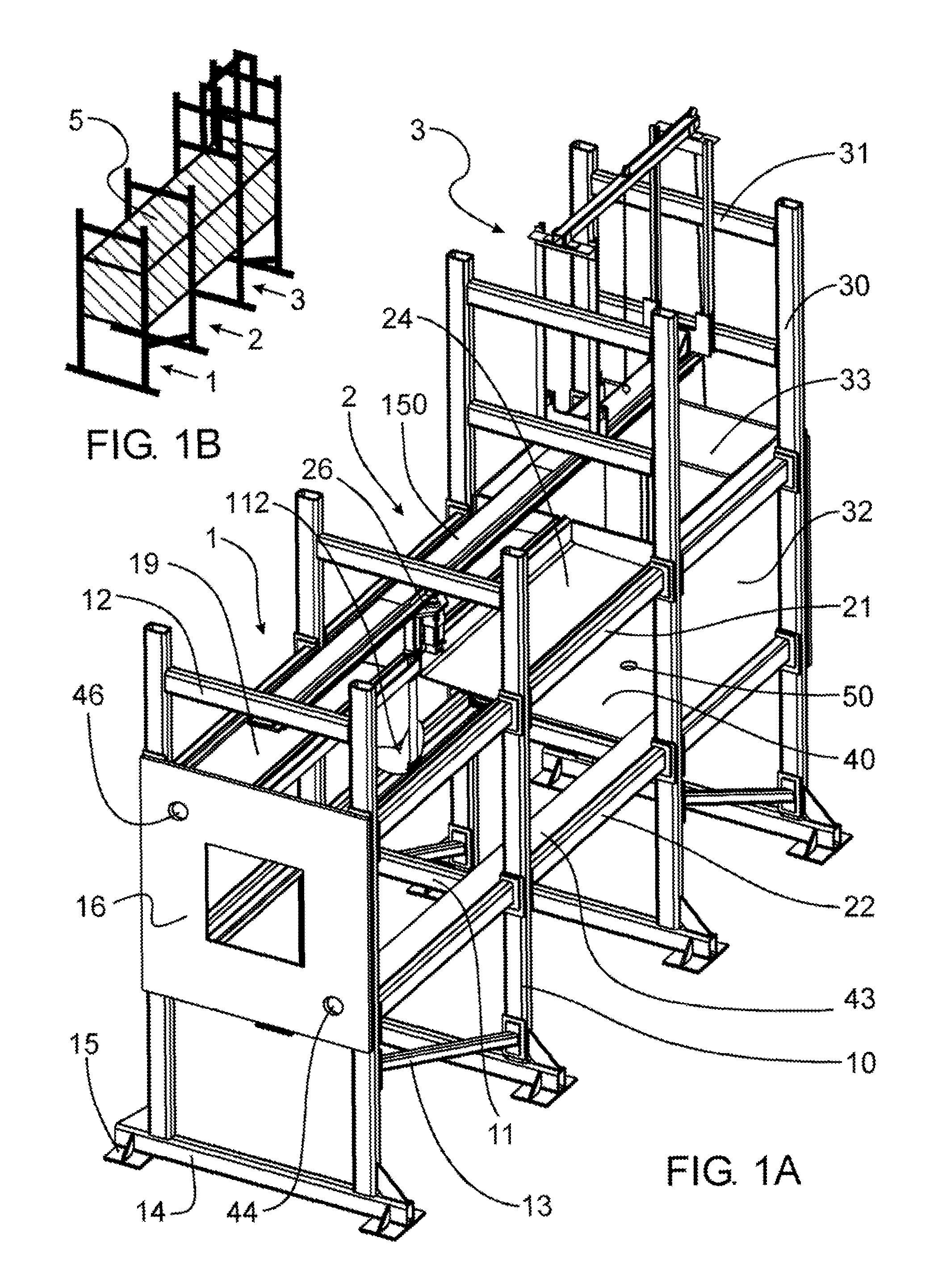
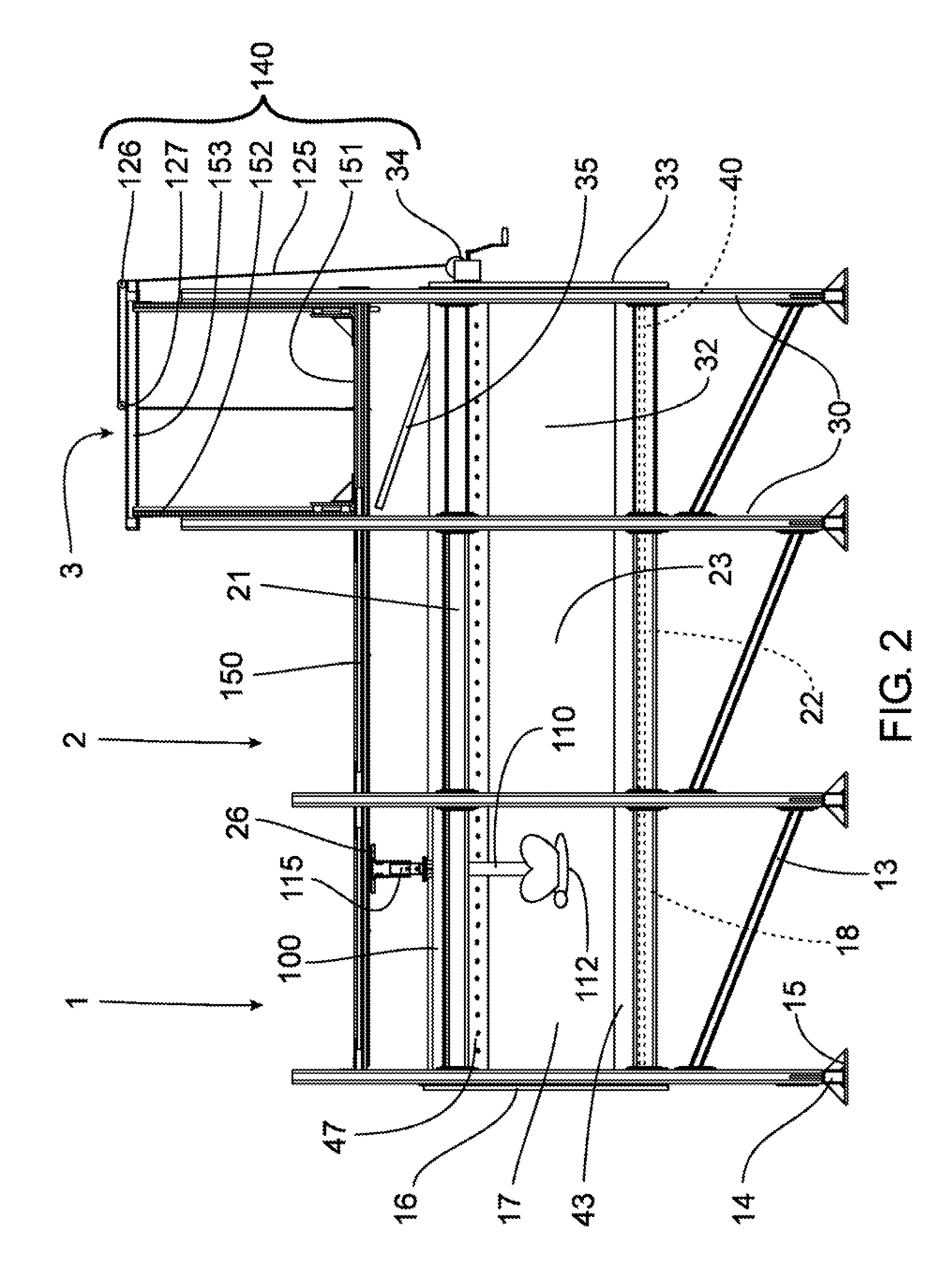
[0032]Generally, the present invention provides an apparatus, designed to conduct aerodynamic and hydrodynamic tests at very low Reynolds numbers, that addresses the problems encountered in conventional facilities when used under these conditions. The apparatus provides an enclosure for a test medium, which substantially eliminates any free surface between the medium and its surroundings, while permitting a model to move through the medium. The fluid contained in the tank is fully surrounded by and in contact with the walls, floor and roof, thereby substantially eliminating the possibility of a free surface. A method of using such an apparatus is also provided.

[0033]Preferably, the test medium is a mixture of two or more liquids where some have high viscosity and others have low viscosity, such that the viscosity of the test medium can be adjusted by changing the ratio between the components.

[0034]A first embodiment of the present invention is shown in FIGS. 1A, 1B, 2, 3A and 3B. Re...


PUM

PropertyMeasurementUnit
viscosityaaaaaaaaaa
kinematic viscosityaaaaaaaaaa

Abstract

An aerodynamic or hydrodynamic test apparatus that permits all air to be evacuated from the test enclosure, such that no free liquid surfaces remain. This permits more accurate testing of structures, particularly at low Reynolds numbers. The apparatus includes a seal that allows the elimination of a liquid free surface. The seal is disposed in a slit on an upper surface of the enclosure and can include one or more inflatable sealing members. The upper surface of the enclosure is preferably sloped upwardly towards the seal to prevent the entrapment of air bubbles within the enclosure. A method of testing using such an apparatus is also disclosed.

Description

CROSS REFERENCE TO RELATED APPLICATIONS[0001]This application is a continuation of application Ser. No. 10 / 493,223, filed Oct. 22, 2004, now abandoned, which claimed priority from U.S. Provisional Application No. 60 / 330,438, filed Oct. 22, 2001.FIELD OF THE INVENTION[0002]The invention relates to the field of aerodynamic and hydrodynamic testing, and more particularly to a method and apparatus for such testing at low Reynolds numbers.BACKGROUND OF THE INVENTION[0003]The traditional approach to aerodynamic testing consists of installing a suitable model of a configuration under study in a wind tunnel and forcing air around it. In the presence of the flow, a variety of physical quantities such as forces, moments, and pressures acting on the model are measured. As well, properties of the flow around the model, such as local velocity, are observed by means of flow visualization and diagnostic techniques.[0004]A frequently used alternate aerodynamic testing approach is based on the use o...

Claims


Application Information

Patent Timeline
Patent Type & Authority Patents(United States)
IPC IPC(8): G01M10/00B63B9/08G01M9/00G01M9/02G01M9/04
CPCG01M9/02G01M10/00G01M9/04
Inventor HANFF, ERNEST S.HUANG, XING ZHONG
Owner NAT RES COUNCIL OF CANADA
Why Eureka
Try Eureka