Pressure detection device
a detection device and pressure technology, applied in the direction of rapid change measurement, fluid pressure measurement using elastically deformable gauges, instruments, etc., can solve the problems of linearity damage, linearity damage in the spring characteristics of the pressure receiving diaphragm b>215/b>, etc., to improve the sensing
- Summary
- Abstract
- Description
- Claims
- Application Information
AI Technical Summary
Benefits of technology
Problems solved by technology
Method used
Image
Examples
first embodiment
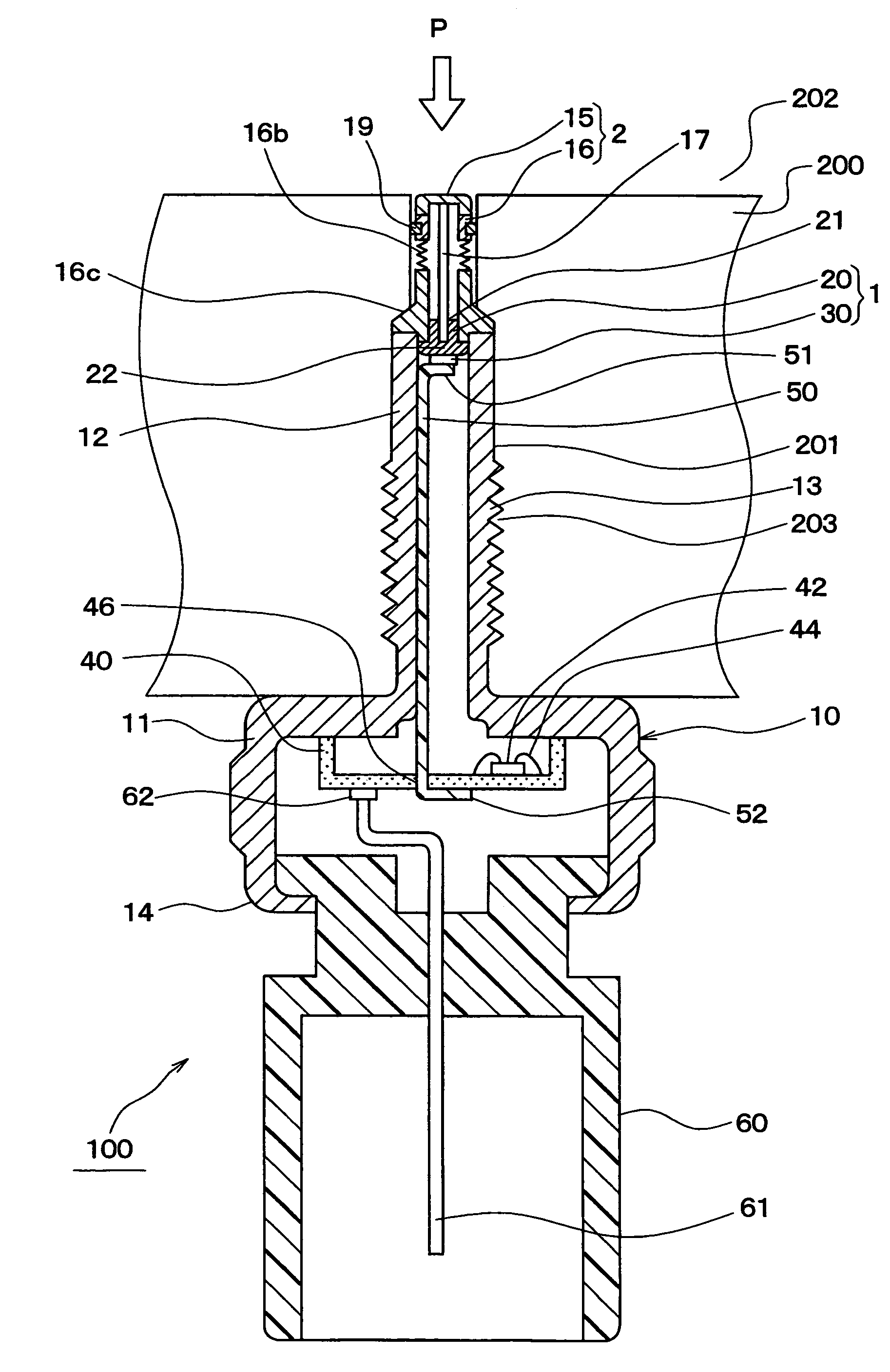
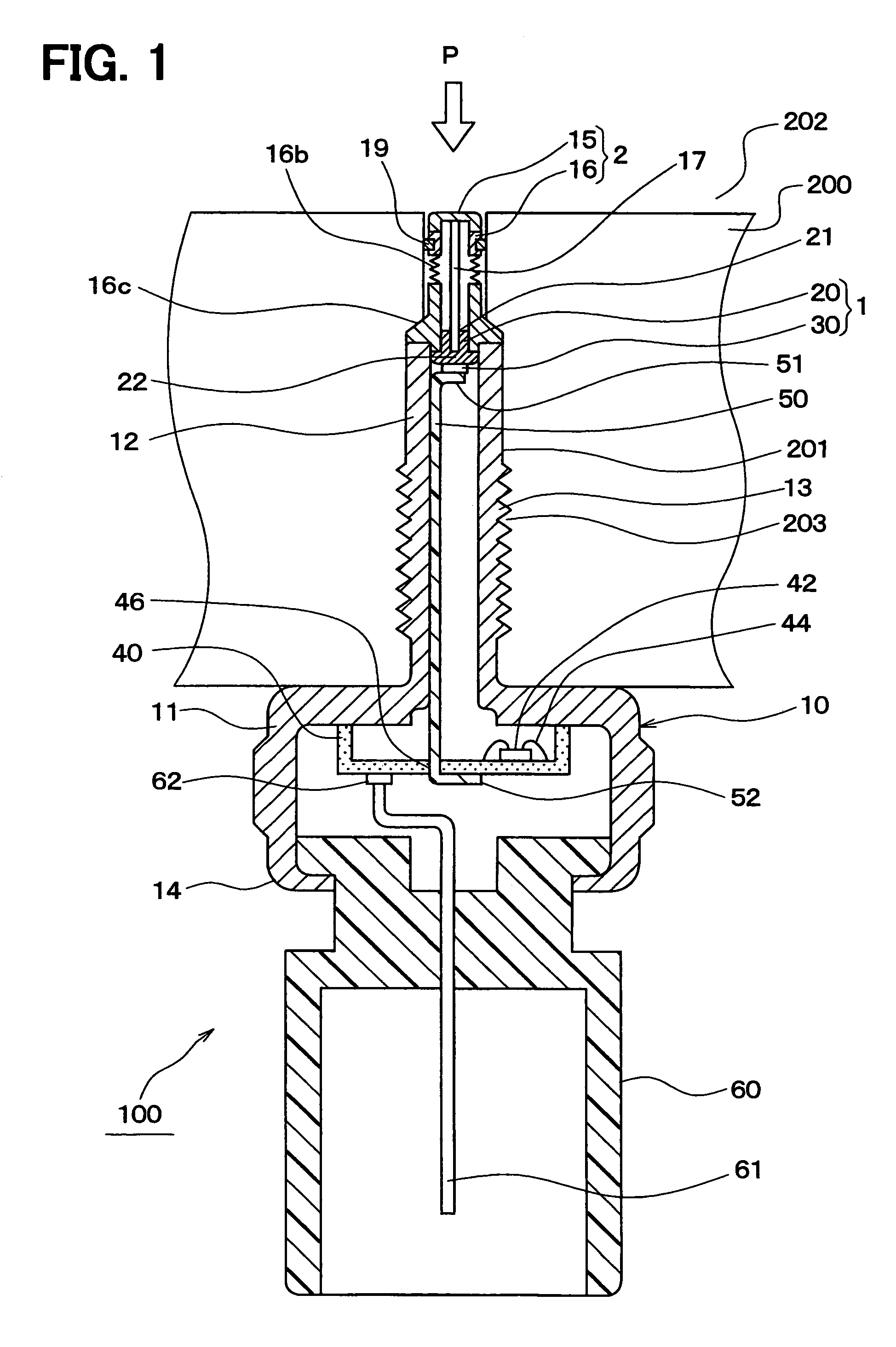
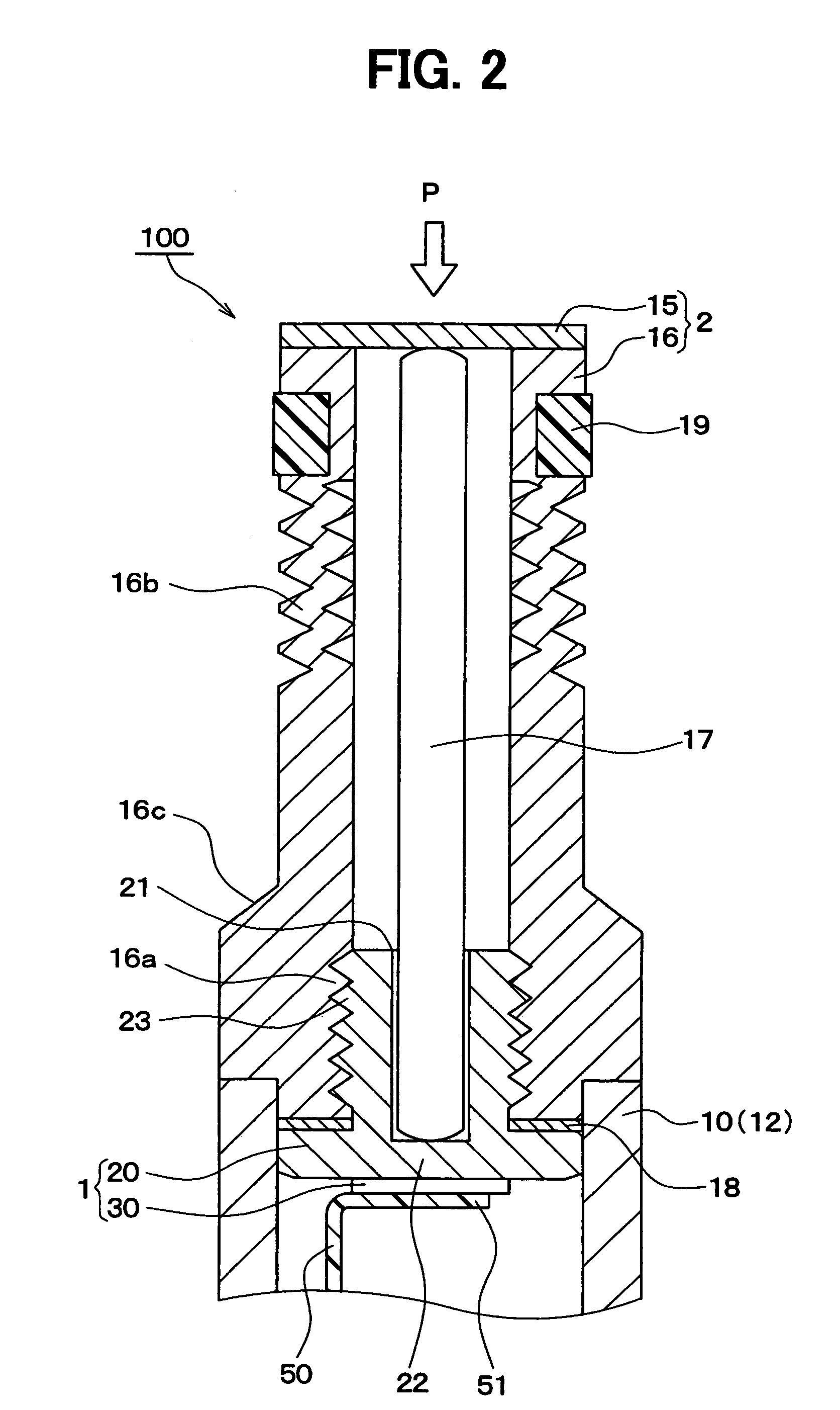
[0059]In this embodiment, a pressure detection device 100 is typically used as a combustion pressure sensor.
[0060]As shown in FIG. 1, in the pressure detection device 100 as a combustion pressure sensor, a pipe portion 12 of a housing 10 is inserted into a threaded hole portion 201 formed in an engine block 200 of an automobile and is jointed thereto by screwing, and senses pressure (cylinder pressure) in a combustion chamber 202 as a detection pressure.
[0061]The housing 10 of the pressure detection device 100 of the present embodiment is constructed of a cylindrical main portion 11 and the slender cylindrical pipe portion 12 which is more slender than the main portion 11.
[0062]These main portion 11 and pipe portion 12 are made of metal, for example, stainless steel by cutting or cold forging. In the present embodiment, the pipe portion 12 is formed in the shape of a cylindrical pipe, but may be formed in the shape of a square pipe.
[0063]In the housing 10, the main portion 11 and th...
second embodiment
[0148]As shown in FIG. 4, a pressure detection device 110 of the present embodiment includes the first part 1 having the detection element 30 as a sensing part, the second part 2 having the pressure receiving diaphragm 15, and the pressure transmission part 17. The first part 1 and the second part 2 are connected to each other, such that the pressure transmission part 17 is interposed between the detection element 30 and the pressure receiving diaphragm 15, and the pressure receiving diaphragm 15 applies a pre-load to the detection element 30 via the pressure transmission part 17.
[0149]In the above-described first embodiment, the first part 1 is constructed of two parts of the detection element 30 and the metal stem 20. However, in the second embodiment, as shown in FIG. 4, the first part 1 is constructed of three parts of the detection element 30, the metal stem 20, and an attachment part 24.
[0150]The metal stem 20, as in the above-described first embodiment, is a hollow cylindrica...
third embodiment
[0184]FIG. 7 shows a pressure detection device 120 of the third embodiment.
[0185]The pressure detection device 120 of the present embodiment is a modification of the pressure detection device of the above-described second embodiment. Specifically, the pressure detection device 120 of the present embodiment is mainly different from the second embodiment in that the installation position of the spring part 70 is changed.
[0186]As shown in FIG. 7, similarly to the pressure detection device 100, 110 in the above-described first embodiment and second embodiment, the pressure detection device 120 of the present embodiment also includes the first part 1 having the detection element 30 as the sensing part, the second part 2 having the pressure receiving diaphragm 15. Further, the pressure transmission part 17 interposed between the detection element 30 and the pressure receiving diaphragm 15, and the first part 1 is coupled to the second part 2 in a state where the pressure receiving diaphra...
PUM
| Property | Measurement | Unit |
|---|---|---|
| pressure | aaaaa | aaaaa |
| flexible | aaaaa | aaaaa |
| cylindrical shape | aaaaa | aaaaa |
Abstract
Description
Claims
Application Information
 - R&D
- Intellectual Property
- Life Sciences
- Materials
- Tech Scout
- Unparalleled Data Quality
- Higher Quality Content
- 60% Fewer Hallucinations
Browse by: Latest US Patents, China's latest patents, Technical Efficacy Thesaurus, Application Domain, Technology Topic, Popular Technical Reports.
© 2025 PatSnap. All rights reserved.Legal|Privacy policy|Modern Slavery Act Transparency Statement|Sitemap|About US| Contact US: help@patsnap.com


