
Horizontal and vertical in-use electrical device cover

a vertical and horizontal technology, applied in the direction of electrical equipment, casings/cabinets/drawers, casings/cabinets/drawers details, etc., can solve the problems of receptacles being open to the elements, prone to damage, and outdoor electrical devices are significantly more susceptible to contamination from dirt, water and other foreign matter than electrical devices located indoors. , to achieve the effect of reducing the size of the outlet and saving spa

Active Publication Date: 2007-12-04
HUBBELL INC
View PDF9 Cites 13 Cited by
  • Summary
  • Abstract
  • Description
  • Claims
  • Application Information

AI Technical Summary

Benefits of technology

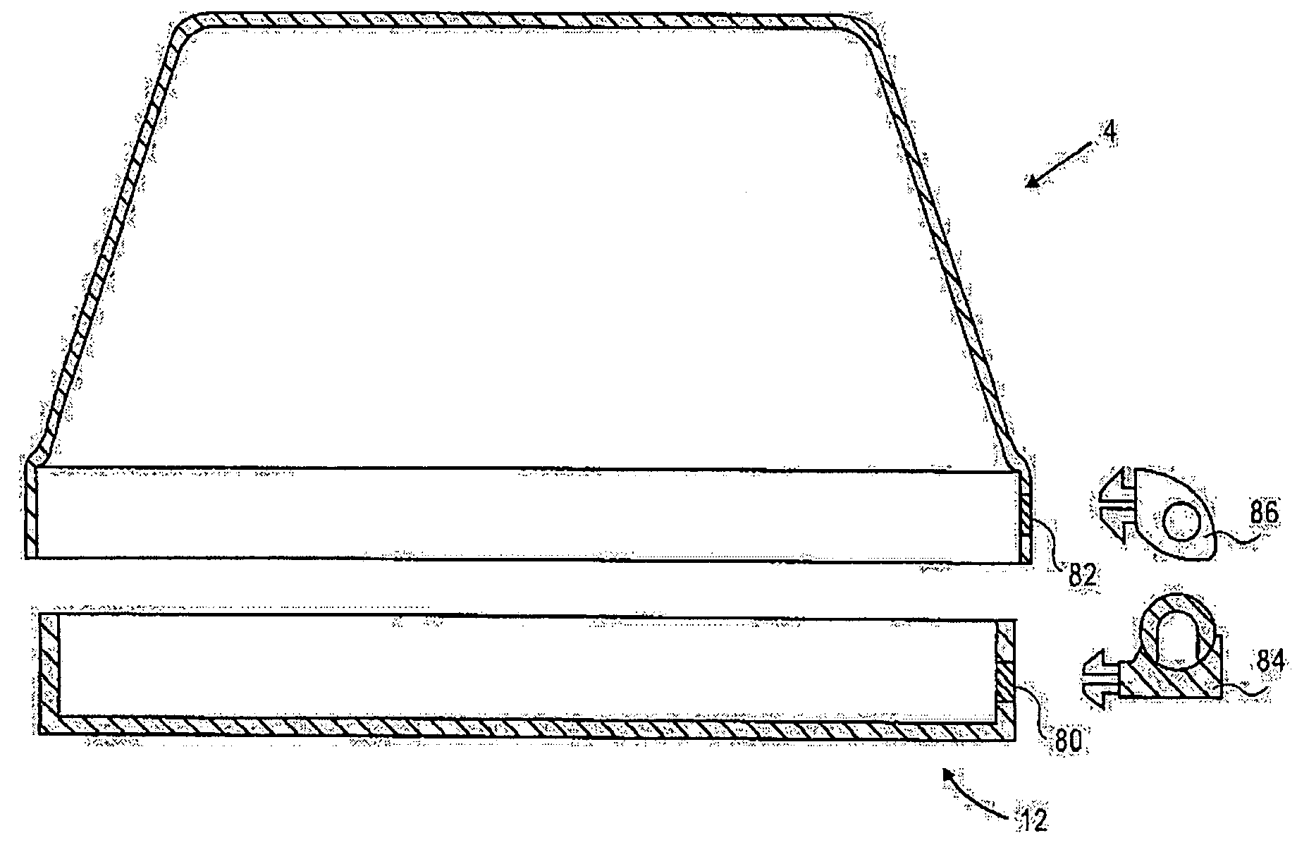
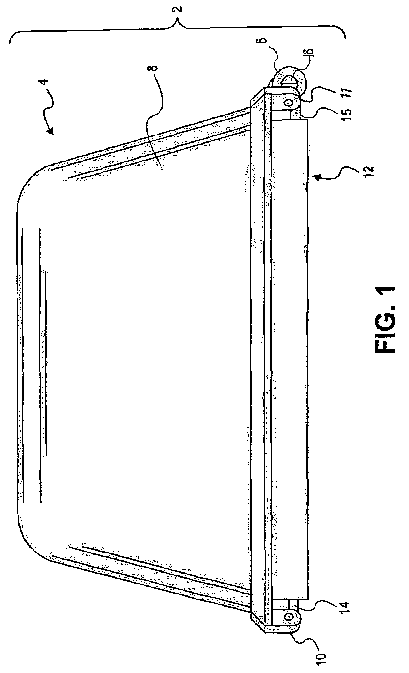
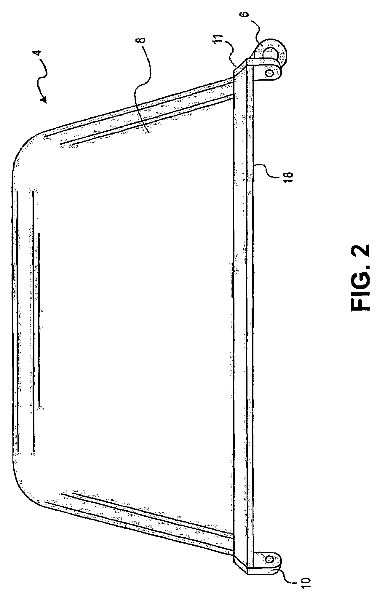
The present invention provides an outlet cover assembly that can be adapted to different materials and methods of creating outlet cover assemblies. The assembly includes a base and a lid that can pivot in two directions, making it more space efficient and a smaller outlet cover. The lid can be closed over the base and plugs with electrical cords can be enclosed. The lid can be opened and closed using a latching mechanism. The invention also allows for horizontal or vertical mounting of the outlet cover assembly using hinge members or a removable pin. The invention provides a more versatile and adaptable outlet cover assembly.

Problems solved by technology

These outdoor electrical devices are significantly more vulnerable to contamination from dirt, water and other foreign matter than electrical devices located indoors.
A major problem with flat electrical outlet covers is that the hinged lids provide protection only while the receptacles are not in use.
As soon as a lid is swung open to allow an electrical appliance to be plugged into a receptacle, that receptacle is open to the elements and vulnerable to damage from moisture and the like.

Method used


Image

  • Horizontal and vertical in-use electrical device cover
  • Horizontal and vertical in-use electrical device cover
  • Horizontal and vertical in-use electrical device cover

Examples


Embodiment Construction

[0053]It will be understood by those of ordinary skill in the art that the invention is not limited to the specific components and assembly procedures disclosed herein. Many additional components and assembly procedures known in the art consistent with the intended electrical outlet cover assembly and / or assembly procedures for an electrical outlet cover assembly will become apparent for use with embodiments of the present invention from the disclosure herein. Accordingly, for example, although particular hardware is disclosed, such hardware and implementing components may comprise any shape, size, style, type, model, version, measurement, concentration, material, quantity, and / or the like as is known in the art for such hardware and implementing components, consistent with the intended operation of assembling an electrical outlet cover assembly. It will also be understood by those of ordinary skill in the art that the invention is not limited to use of any specific components, prov...


PUM


Abstract

A plurality of approaches for forming a horizontal and vertical electrical device cover including 1) providing hinge members on opposing sides of the cover that allow the cover to pivot along adjacent-sided axes for horizontal and vertical mounting; 2) providing a removable pin and corresponding cover and base hinge members wherein the removable pin may be placed along either the horizontal or vertical axis for selective horizontal or vertical mounting; 3) providing a pivoting hinge arm that is pivotable between adjacent sides of the unit for selective horizontal or vertical mounting; and 4) providing selectively attachable hinge members that may be attached by the installer at the time of installation to choose between horizontal or vertical mounting configurations.

Description

RELATED APPLICATIONS[0001]This application is a continuation of U.S. patent application to Michael J. Shotey, et al entitled “Horizontal and Vertical In-Use Electrical Device Cover,” Ser. No. 11 / 062,030, filed Feb. 18, 2005 now U.S. Pat. No. 7,071,415, the disclosure of which is hereby incorporated herein by reference. That application claims priority to the following, the disclosures of which are each also hereby incorporated herein by reference: U.S. Provisional Patent Application to Michael J. Shotey, et al entitled “Outlet Cover with Snap-on Hinges,” Ser. No. 60 / 546,837, filed Feb. 19, 2004; U.S. Provisional Application to Michael J. Shotey, et al entitled “Horizontal and Vertical In-use Electrical Outlet Cover,” Ser. No. 60 / 567,378, filed on Apr. 30, 2004; U.S. Provisional Application to Michael J. Shotey, et al entitled “Horizontal and Vertical In-use Electrical Outlet Cover with Pin Hinge,” Ser. No. 60 / 592,567, filed on Jul. 30, 2004; and U.S. Provisional Application to Micha...

Claims


Application Information

Patent Timeline
Patent Type & Authority Patents(United States)
IPC IPC(8): H02G3/14
CPCH02G3/14
Inventor SHOTEY, MICHAEL J.SHOTEY, MARCUS J.BOOTH, KENNETH C.KINNARD, JOHNMALTBY, EDGAR W.
Owner HUBBELL INC
Learn More