Manufacturing device of electric wire with terminal and manufacturing method of electric wire with terminal

a manufacturing method and technology of electric wire, applied in the direction of manufacturing tools, other manufacturing equipment/tools, connection formation by deformation, etc., can solve the problems of reducing the flexibility or eliminating the flexibility of the electric wire holding portion movemen

Inactive Publication Date: 2007-12-11
JST MFG CO LTD
View PDF13 Cites 10 Cited by
  • Summary
  • Abstract
  • Description
  • Claims
  • Application Information

AI Technical Summary

Benefits of technology

[0013]According to the invention, relative movements between the terminal crimping portion and the electric wire holding portion to supply the electric wires to the terminal crimping portion can be achieved by the crimping portion moving mechanism. This can lower the degree of flexibility or eliminate the flexibility in movements of the electric wire holding portion. It is thus possible to simplify the structures of the electric wire holding portion and the mechanism to move the electric wire holding portion. In addition, the movable range of the terminal crimping portion can be far smaller than a movable range of the transportation device adopting the transfer method, which is as large as the overall manufacturing device of an electric wire with terminal. The manufacturing device of an electric wire with terminal can be therefore reduced in size. Also, because plural crimping positions can be set along the crimping portion moving direction, for example, by moving the terminal crimping portion while plural electric wires are aligned and held by the electric wire holding portion, it is possible to crimp the terminal fittings successively onto the plural electric wires. Moreover, because this advantage can be achieved with the use of the crimping portion moving mechanism, for example, the need to move the electric wire holding portion in the direction along which the electric wires are aligned can be eliminated. This can in turn prevent the electric wire holding portion from becoming complicated in structure and hence from increasing in size. These configurations are therefore preferable to reduce the manufacturing device of an electric wire with terminal in size.
[0023]In the manufacturing method of the invention, it is preferable that the plural electric wires are coated electric wires each formed by coating a core wire with a coating portion made of a resin material, and in this case, it is preferable to further include a coating removing step of removing the coating portions from the end portions of the plural electric wires using strip blades that make incisions in the coating portions, which is performed before the electric wire holding step. It is also preferable that the coating removing step includes an incision depth adjusting step of adjusting an incision depth to be made by the strip blades depending on kinds of electric wires from which the coating portions are to be removed. When configured in this manner, incision depths that best suit the electric wires of respective kinds can be readily obtained. Moreover, because the strip mechanism can be used commonly to remove the coating portions from plural kinds of electric wires, the manufacturing device of an electric wire with terminal adopting this manufacturing method can be reduced further in size.

Problems solved by technology

This can lower the degree of flexibility or eliminate the flexibility in movements of the electric wire holding portion.

Method used


Image

  • Manufacturing device of electric wire with terminal and manufacturing method of electric wire with terminal
  • Manufacturing device of electric wire with terminal and manufacturing method of electric wire with terminal
  • Manufacturing device of electric wire with terminal and manufacturing method of electric wire with terminal

Examples


Embodiment Construction

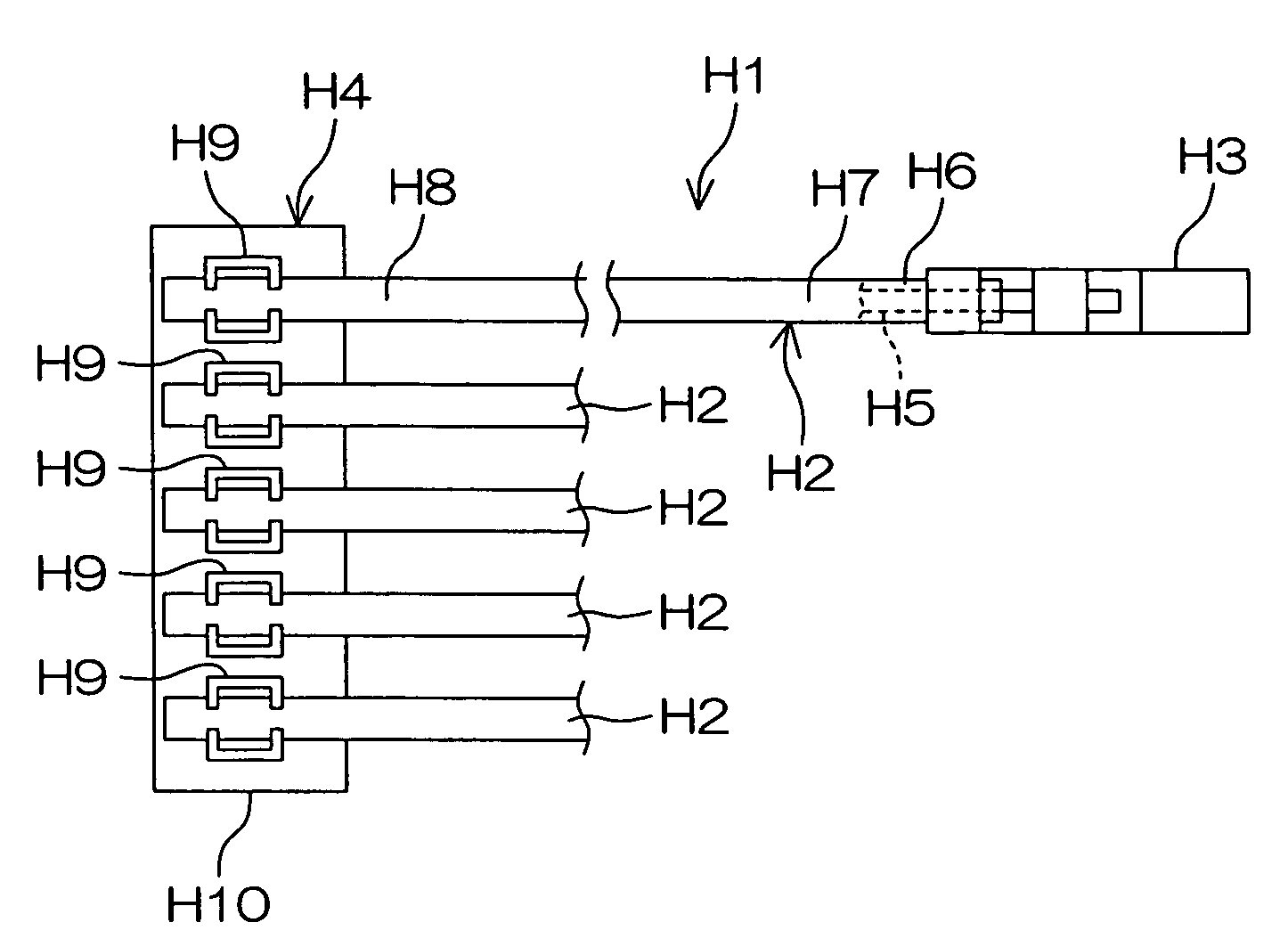
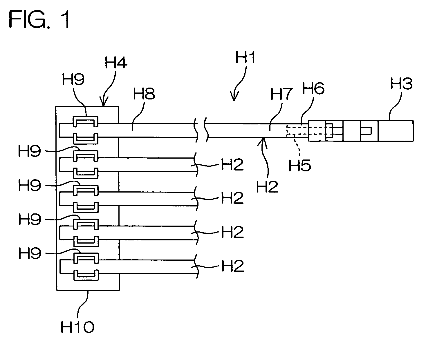
[0050]A wire harness manufactured as electric wires with terminals by a manufacturing device of an electric wire with terminal according to one embodiment of the invention will be described first. FIG. 1 is a schematic view of a wire harness.

[0051]A wire harness H1 has at least one, for example, five electronic wires H2, at least one, for example, five terminal fittings H3 (only one of them is shown), and one insulation displacement termination connector H4.

[0052]Each electric wire H2 is a coated electric wire formed by coating a core wire H5 made of a conductor with a coating portion H6 made of a resin material.

[0053]The terminal fittings H3 are crimped onto one end portions H7 of at least one of plural electric wires H2, for example, five electric wires H2. Each terminal fitting H3 includes a barrel serving as a connection portion to be connected to the electric wire H2 by crimping. The barrel comprises, for example, an open barrel having a pair of caulking pieces, and the electri...


PUM

PropertyMeasurementUnit
heightaaaaaaaaaa
depthaaaaaaaaaa
length measuringaaaaaaaaaa

Abstract

A terminal crimping device is used to manufacture an electric wire with terminal by crimping a terminal fitting onto an end portion of an electric wire. This device includes: an electric wire holding portion to hold the end portion of the electric wire at a predetermined crimping position; a terminal crimping portion to crimp the terminal fitting onto the end portion of the electric wire at the crimping position; and a crimping portion moving mechanism to move the terminal crimping portion along a crimping portion moving direction. The terminal crimping portion is provided to be movable with respect to the end portion of the electric wire held at the crimping position by the electric wire holding portion along the crimping portion moving direction that intersects with a direction along which the end portion of the electric wire extends.

Description

BACKGROUND OF THE INVENTION[0001]1. Field of the Invention[0002]The present invention relates to a manufacturing device of an electric wire with terminal and a manufacturing method of an electric wire with terminal for crimping a terminal fitting onto an end portion of an electric wire.[0003]2. Description of Related Art[0004]A manufacturing device of an electric wire with terminal having a top force and a bottom force opposing each other to crimp a terminal fitting onto an end portion of an electric wire, a press mechanism to caulk the terminal fitting by moving the top force and the bottom force closer or spaced apart, and a base member to support the press mechanism in a fixed state, is known in the related art (for example, Japanese Laid-open Patent Application (KOKAI) Nos. 8-315950 and 9-306629).[0005]A typical example of a product using an electric wire with terminal is a wire harness. The wire harness is manufactured, for example, by crimping plural terminal fittings to one e...

Claims


Application Information

Patent Timeline
Patent Type & Authority Patents(United States)
IPC IPC(8): B23P19/00H01R43/048H01R4/10H01R43/05
CPCH01R43/05Y10T29/515Y10T29/53235Y10T29/53217H01R43/048
Inventor KUROOKA, KAZUMAONISHI, JUNJIMINOMURA, SHIGEONISHIURA, MASATAKA
Owner JST MFG CO LTD
Why Eureka
Try Eureka