Portable power tool

a portable power tool and tool body technology, applied in the field of hand power tools, can solve the problem that the unlocking unit cannot be reliably tripped, and achieve the effect of high operating safety

Inactive Publication Date: 2007-12-11
ROBERT BOSCH GMBH
View PDF13 Cites 15 Cited by
  • Summary
  • Abstract
  • Description
  • Claims
  • Application Information

AI Technical Summary

Benefits of technology

[0006]It is proposed that a gear is actuatable via an on / off switch means for actuating the unlocking unit. Thus the unlocking unit can be reliably tripped upon activation of the electric motor. The user's actuation force unlocks the guard device. The unlocking unit therefore requires no complicated electronic components and is especially fail-safe. Moreover, mechanical components are inexpensive and require no electrical power. The guard device can be tripped in the event of an uncontrollable blockage and reset and re-activated without particular effort when the hand power tool is switched back on again. Compared with electrical or electronic systems, the function of the guard device is simplified considerably. The mechanically actuatable unlocking unit can be combined with mechanical, electrical and electronic variants of sensor units and / or blocking units of a guard device. The gear can preferably be embodied as a cam gear. Optionally, a lever mechanism or some other mechanism that is considered appropriate by one skilled in the art may be provided. Especially advantageously, the on / off switch means is embodied as a switching latch, which is actuated by the user for switching the hand power tool on and off. Alternatively, the on / off switch means can also be integrated with the hand power tool in such a way that it is tripped when the tool or the hand power tool is pressed against a surface to be machined.
[0021]If the electric motor and / or electrical components are capable of being switched off in the event of blockage, then energy can be saved. For manually unlocking the unlocking unit, the electric motor is already switched off, and the user can rapidly put the hand power tool back into operation. If the electric motor is switched off and an electric clutch is opened in order to interrupt the flow of torque in the event of a blockage, it can be assured that the housing remains blocked in its motion.

Problems solved by technology

Thus the unlocking unit can be reliably tripped upon activation of the electric motor.

Method used


Image

  • Portable power tool
  • Portable power tool
  • Portable power tool

Examples


Embodiment Construction

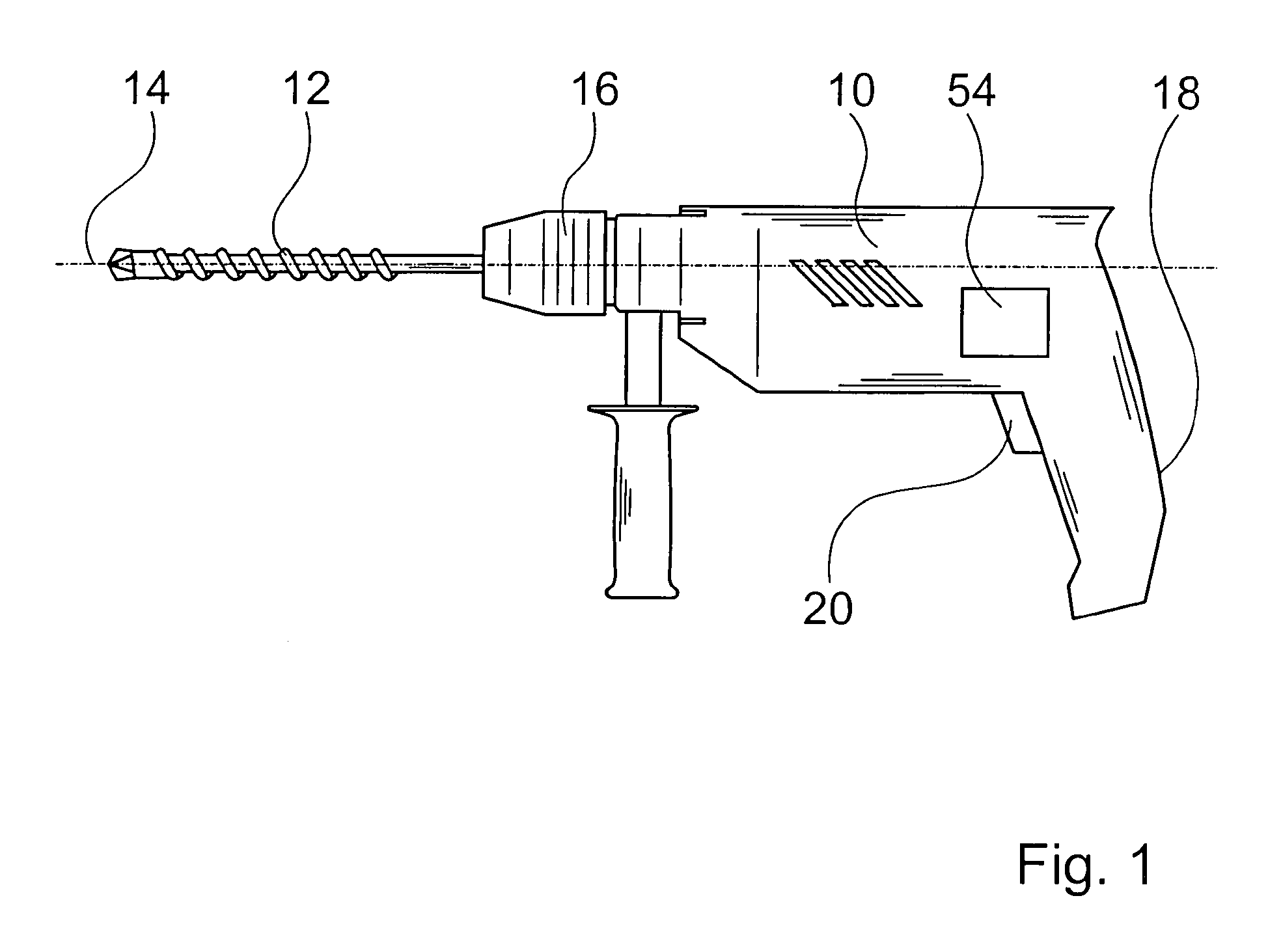
[0027]FIG. 1 shows a hand power tool, with an electric motor, not shown, located in a housing 10. The electric motor drives a tool insert 12, located in a tool retainer 16, to rotate. A guard device 54 can be unlocked with an on / off switch means 20, embodied as a switching latch of an on / off switch, in a grip 18 of the hand power tool. If an uncontrollable blockage occurs, there is the risk that the housing 10 will rotate about an axis of rotation 14.

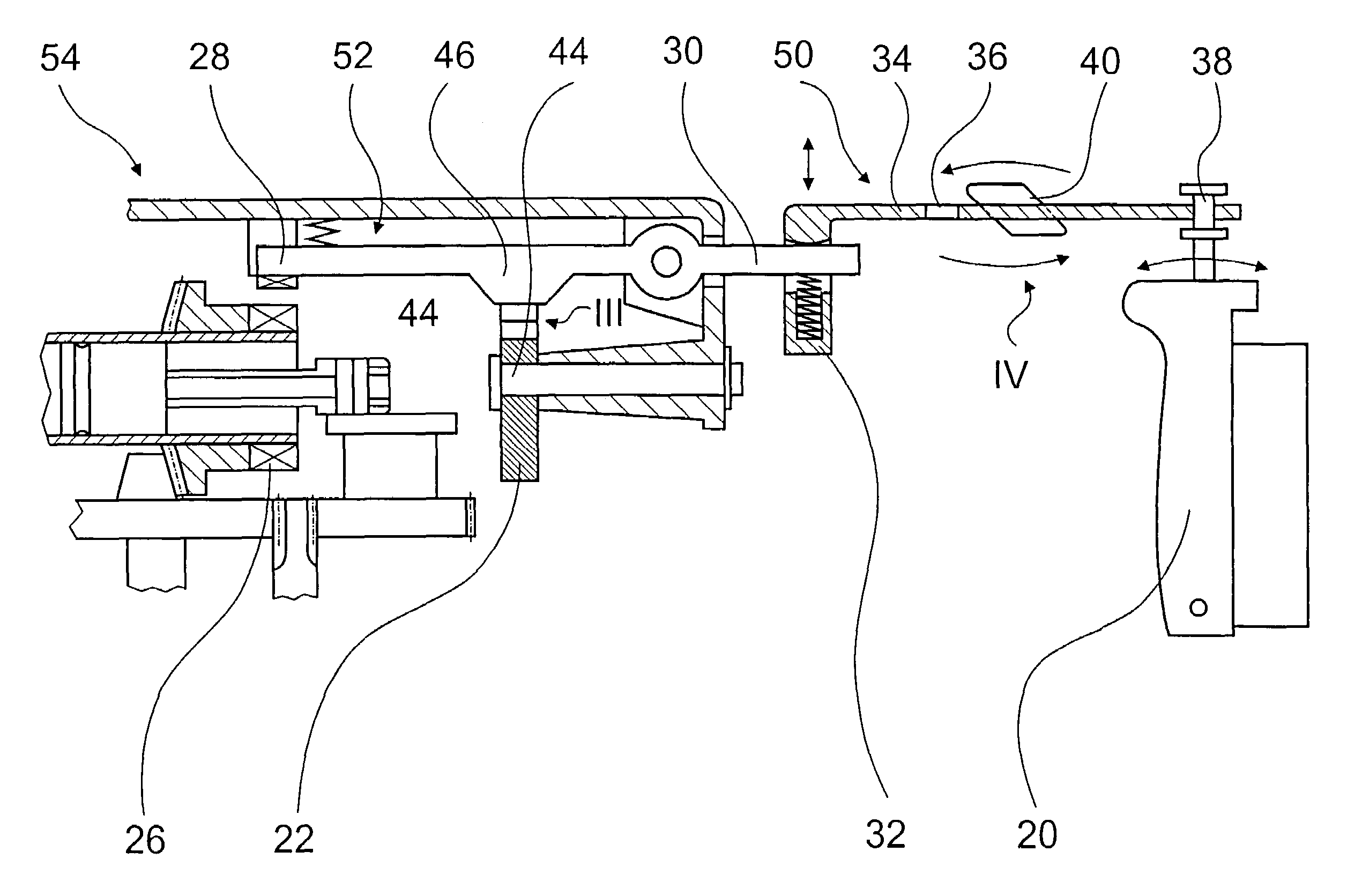
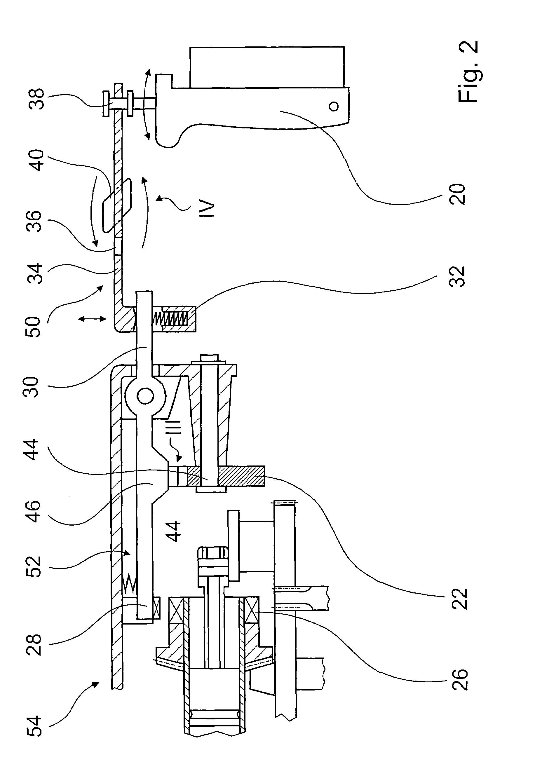
[0028]With the guard device 54, an uncontrollable blockage of the tool insert 12 can be detected via a sensor unit 22, and the housing 10 can be blocked in its motion; preferably, the electric motor is switched off. A preferred guard device 54 is shown in FIG. 2. A mechanical sensor unit 22 is operatively connected to a mechanical blocking unit 52. An especially preferred blocking unit 52 and the sensor unit 22 are described in Published German Patent Disclosure DE 43 00 021, whose disclosure is hereby expressly incorporated herein by r...


PUM

PropertyMeasurementUnit
actuating forceaaaaaaaaaa
displacementaaaaaaaaaa
torqueaaaaaaaaaa

Abstract

A hand power tool has an electric motor, which is located in a housing and by way of which a tool insert located in a tool retainer is drivable in rotation, a guard device with which an uncontrollable blockage of the tool insert is detectable via a sensor unit and with which the housing is blockable in its motion; the guard device includes a mechanical unlocking unit that is manually actuatable by a user's action force, and gear is actuatable via an on / off switch for actuating the unlocking unit.

Description

CROSS-REFERENCE TO A RELATED APPLICATION[0001]The invention described and claimed hereinbelow is also described in German Patent Application DE 10353013.4 filed on Nov. 13, 2003. This German Patent Application provides the basis for a claim of priority of invention under 35 U.S.C. 119(a)-(d).BACKGROUND OF THE INVENTION[0002]The invention is based on a hand power tool.[0003]An uncontrollable blockage of a hand power tool exists if the tool insert seizes in the workpiece to be machined, the reaction torque operative at the housing exceeds a user's grasping force, and the housing rotates uncontrollably at a defined angular speed and over a defined angular range about an axis. If the user's grasping force is greater than the existing reaction torque, or if the user is grasping the hand power tool firmly during a blockage, then a so-called controllable blockage is involved.[0004]From German Published Patent Disclosure DE 37 07 052 A1, a hand power tool is known that has an electric motor...

Claims


Application Information

Patent Timeline
Patent Type & Authority Patents(United States)
IPC IPC(8): E21B15/04B25F5/00
CPCB25F5/00
Inventor MEIXNER, GERHARDLEUPERT, MARKUS
Owner ROBERT BOSCH GMBH
Why Eureka
Try Eureka