Hybrid transmission and mode-shift control for hybrid vehicle

a hybrid vehicle and transmission technology, applied in the direction of electric propulsion mounting, machines/engines, gearing, etc., can solve the problems of causing a and similar shift shock or uncomfortable feeling may also happen, so as to prevent a potential shift shock and uncomfortable feeling

Inactive Publication Date: 2007-12-11
NISSAN MOTOR CO LTD
View PDF20 Cites 43 Cited by
  • Summary
  • Abstract
  • Description
  • Claims
  • Application Information

AI Technical Summary

Benefits of technology

[0004]Accordingly, it is an object of the present invention to provide a hybrid transmission with which the driving mode can be smoothly shifted with no rapid change of the operating state of the hybrid transmission to prevent a potential shift shock and uncomfortable feeling during a mode shift including a change of the engagement state of torque transmitting mechanism such as an engine clutch and a brake, and also during other mode-shifts with no change of the engagement state of torque transmitting mechanism.

Problems solved by technology

A hybrid transmission including an engine clutch between an engine and an associated rotating member of a differential mechanism as discussed above has a potential of causing a shift shock or uncomfortable feeling, when the driving mode is shifted with a shift of the state of an engine clutch between an engaged state and a disengaged state to change rapidly the operating state of the hybrid transmission.
Similar shift shock or uncomfortable feeling may also happen during the operating state of the hybrid transmission being rapidly changed with no change of the engagement state of the engine clutch.

Method used


Image

  • Hybrid transmission and mode-shift control for hybrid vehicle
  • Hybrid transmission and mode-shift control for hybrid vehicle
  • Hybrid transmission and mode-shift control for hybrid vehicle

Examples


Embodiment Construction

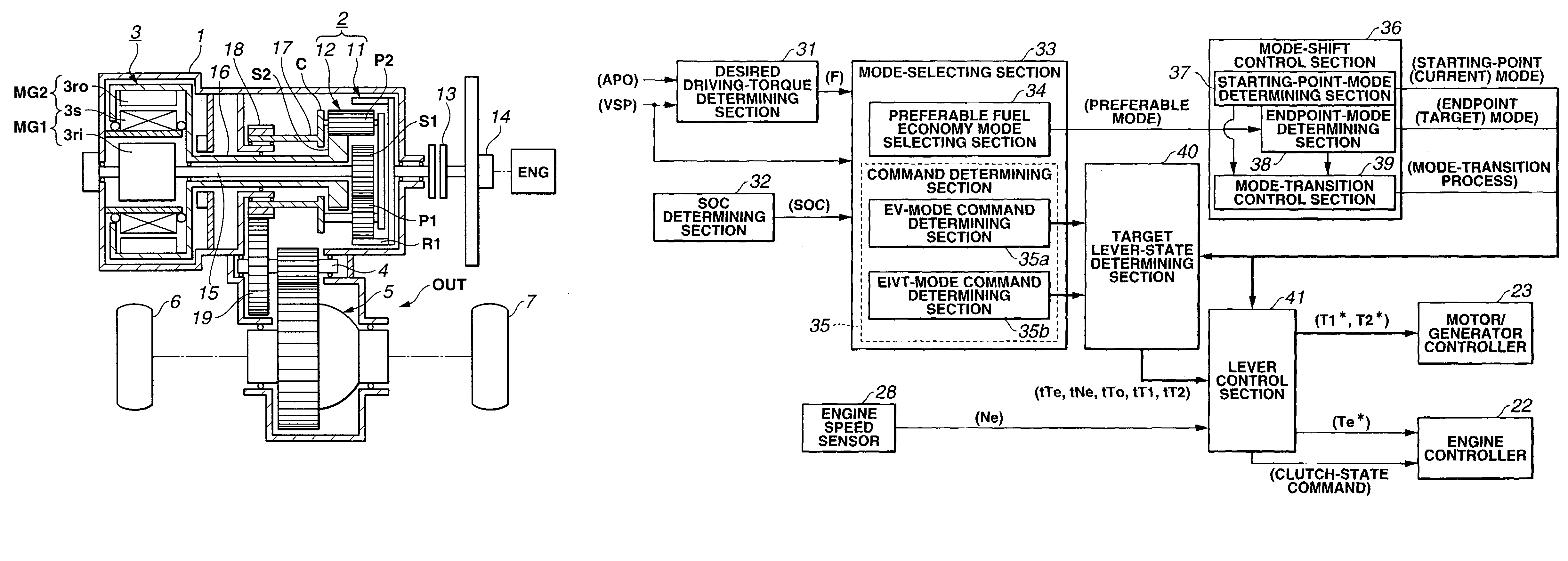
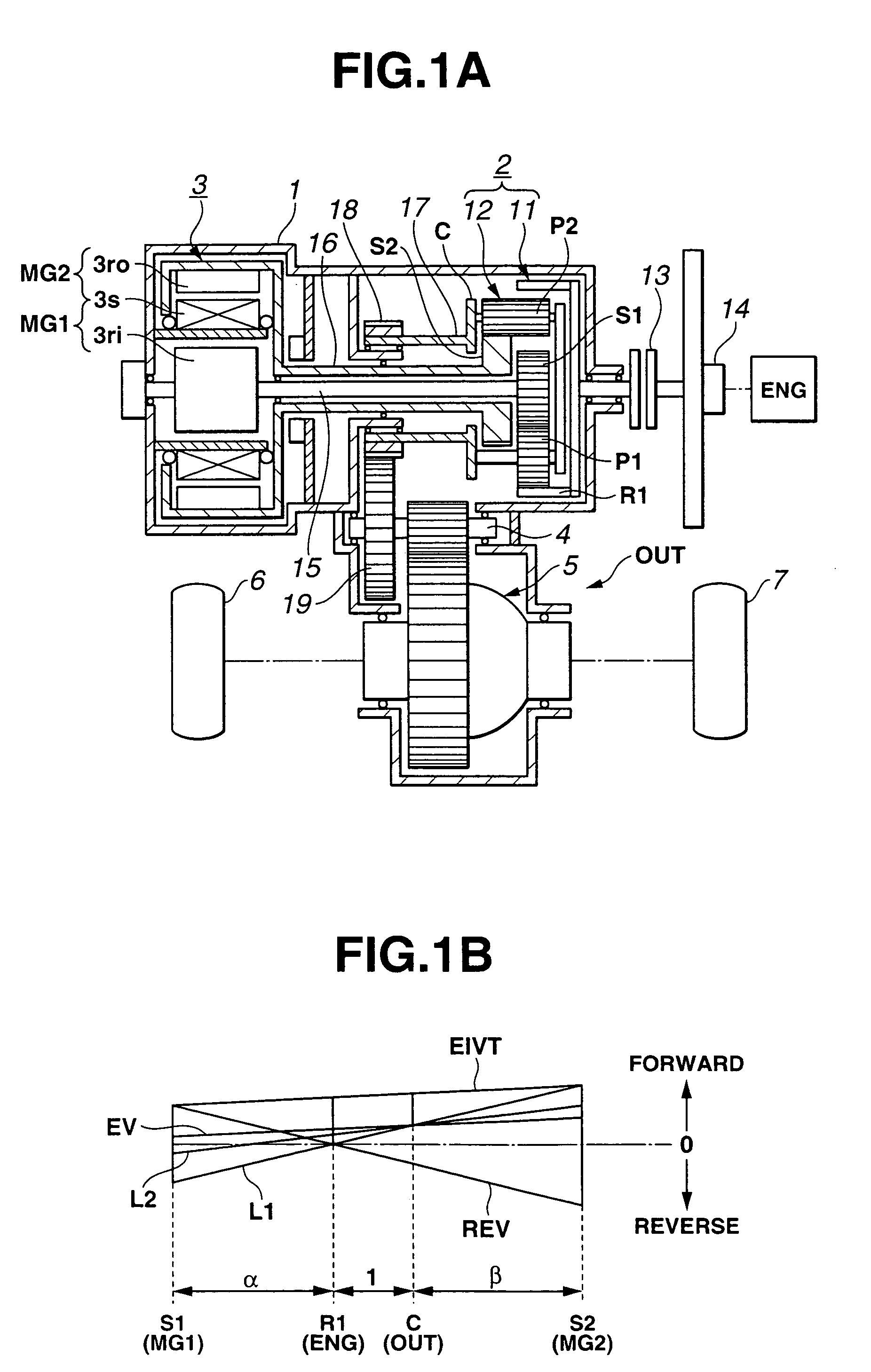
[0017]Referring now to FIG. 1A, there is shown a hybrid transmission for a hybrid vehicle mounting thereon a plurality of motors in accordance with an embodiment of the present invention. In this embodiment, the hybrid transmission includes motors including an ICE and two electric motors and serves for a front transaxle of a front engine, front wheel drive vehicle (FF vehicle). The hybrid transmission includes a transmission housing 1 formed into a combination of three cylindrical shapes. In a cylinder of transmission housing 1, a Ravigneaux planetary gearset 2 is located at the right of the longitudinal axis (the horizontal direction in FIG. 1A) of the cylinder of transmission housing 1, and a compound multiphase alternating current (AC), multi-layer motor such as a compound-current double-layer motor 3 is coaxially located at the left. At the right side of Ravigneaux planetary gearset 2 and outside transmission housing 1 is located a prime mover such as an internal combustion engi...


PUM


Abstract

A hybrid transmission for a hybrid vehicle mounting thereon an engine and a pair of electric motor / generators operates in a plurality of driving modes including EV mode in which the vehicle is powered by only the pair of motor / generators and EIVT mode in which the vehicle is powered by both the pair of motor / generators and the engine. The driving mode is shifted continuously and smoothly through a mode-shift transition process, in which the operating state is regulated to decrease the relative torque and / or the relative rotational speed between the contact elements of an engine clutch before engaging or disengaging the engine clutch.

Description

BACKGROUND OF THE INVENTION[0001]The present invention relates generally to hybrid transmissions suitable for hybrid electric vehicles (HEVs) equipped with a prime mover such as an internal combustion engine (ICE) and a motor / generator, and more particularly to a hybrid transmission including a differential mechanism between a prime mover and a motor / generator for continuously variable speed control.[0002]In recent years, there have been disclosed various hybrid transmissions. One such hybrid transmission has been disclosed in Japanese Patent Provisional Publication No. 2003-034154. The hybrid transmission includes a two-degree-of-freedom differential mechanism including a compound planetary gearset. The rotating members of the differential mechanism are connected to a prime mover such as an ICE as an input element, a drive train as an output element, and a pair of motor / generators for continuously variable speed control. In addition, an engine clutch is disposed between the ICE and...

Claims


Application Information

Patent Timeline
Patent Type & Authority Patents(United States)
IPC IPC(8): B60K6/00B60K1/02B60W20/00B60K6/445B60L50/16B60W10/00B60W10/02B60W10/04B60W10/06B60W10/08B60W10/10F02D29/02F16H59/54F16H59/56F16H59/68F16H59/74F16H61/04F16H63/50
CPCB60K6/365B60K6/445B60W10/02B60W10/06B60W10/08F16H3/727B60W20/00B60K1/02Y02T10/6239F16H2037/103Y02T10/6286Y10S903/93Y10S903/946Y02T10/62B60W20/40B60W20/11
Inventor IMAZU, TOMOYAJOE, SHINICHIROMENSLER, MICHEL
Owner NISSAN MOTOR CO LTD
Why Eureka
Try Eureka