

Fixing method of in-wheel motor and in-wheel motor system
a technology of in-wheel motors and fixed methods, which is applied in mechanical energy handling, transportation and packaging, electric propulsion mounting, etc., can solve the problems of deteriorating road holding properties, so as to reduce the fluctuation of tire contact force of vehicles and improve the road holding properties of vehicles
- Summary
- Abstract
- Description
- Claims
- Application Information
AI Technical Summary
Benefits of technology
Problems solved by technology
Method used
Image

Examples
embodiment 1
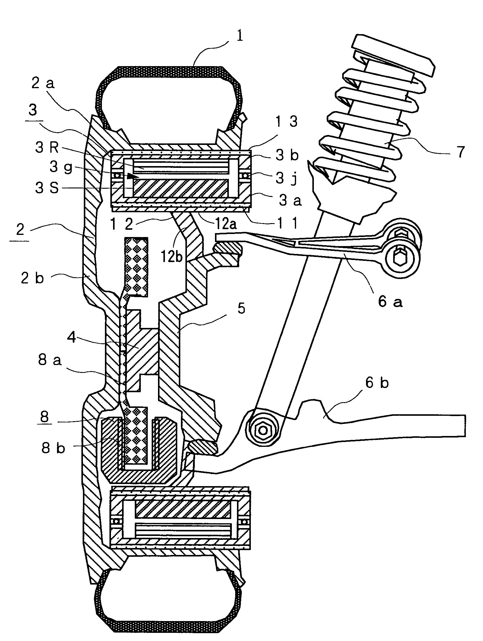
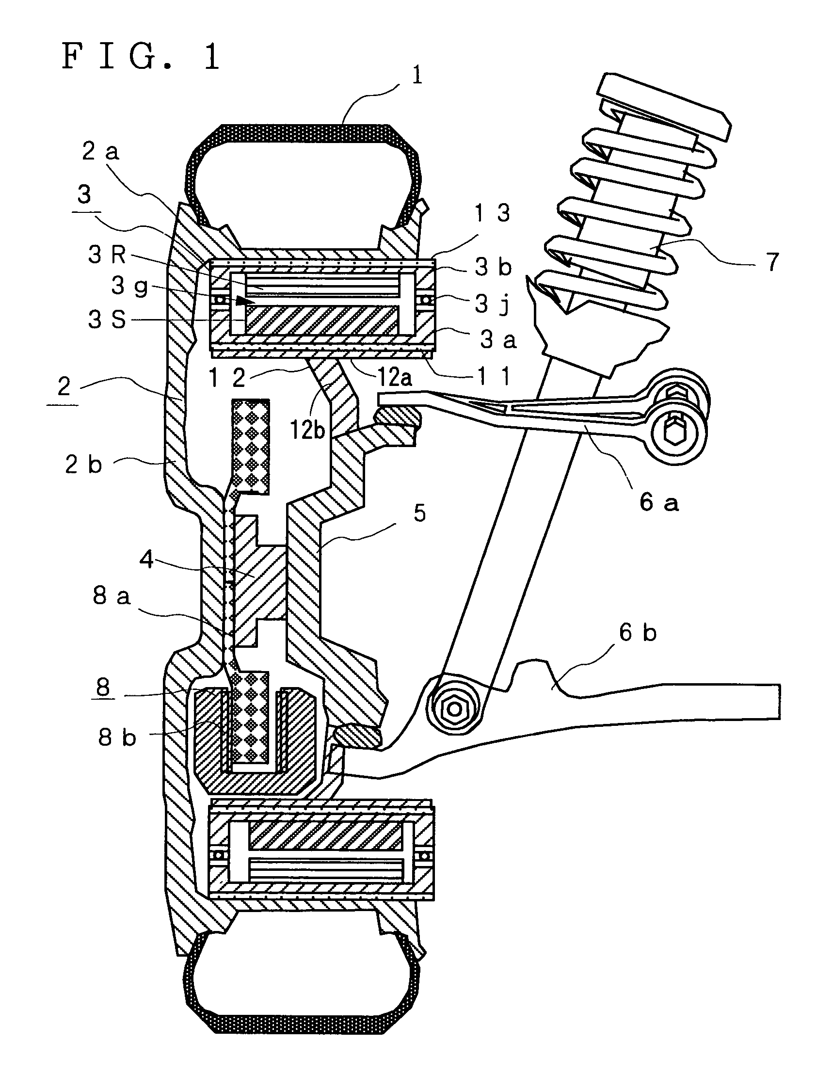
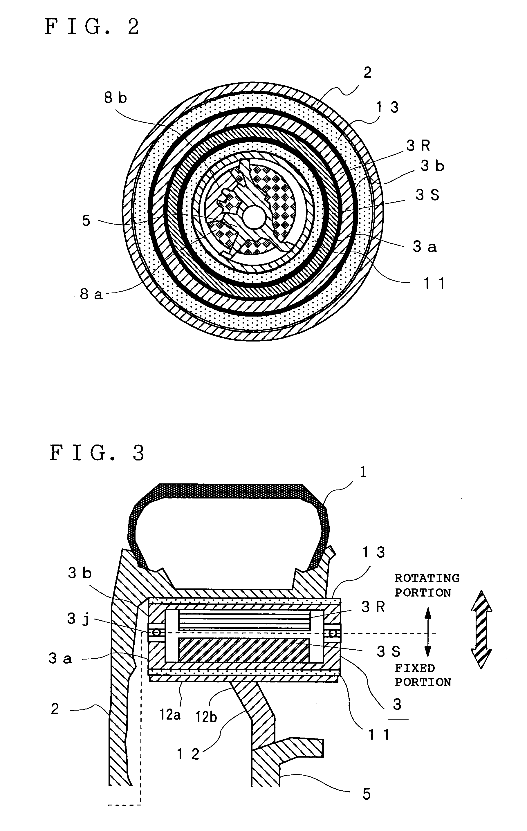
[0155]FIG. 1 and FIG. 2 are diagrams showing the constitution of an inwheel motor system according to Embodiment 1 of the present invention. FIG. 1 is a longitudinal sectional view and FIG. 2 is a front sectional view of the inwheel motor system. In these figures, reference numeral 1 denotes a tire, 2 denotes a wheel consisting of a rim 2a and a wheel disk 2b, and 3 denotes an inwheel motor of an outer rotor type comprising a motor stator (to be simply referred to as “stator” hereinafter) 3S fixed to a non-rotary case 3a provided on the inner side in a radial direction and a motor rotor (to be simply referred to as “rotor” hereinafter) 3R fixed to a rotary case 3b rotatably fixed to the above non-rotary case 3a through a bearing 3j and provided on the outer side in the radial direction. An air gap 3g is formed between the above rotor 3R and the above stator 3S. Reference numeral 4 represents a hub portion connected to the rotation axis of the above wheel 2, 5 represents a knuckle co...
embodiment 2
[0176]In the above Embodiment 1, the rotary case 3b and the wheel 2 are interconnected by the second elastic member 13. As shown in FIG. 14 and FIG. 15, the above rotary case 3b may be connected to the wheel 2 by the second elastic member 13 and a constant-velocity universal joint 16.
[0177]That is, when the rotary case 3b and the wheel 2 are interconnected by an elastic member as in the above Embodiment, a phase difference is produced between the wheel 2 and the rotary case 3b by shear deformation in the circumferential direction. Therefore, the above rotary case 3b and the wheel 2 are interconnected by the above second elastic member 13 and the constant-velocity universal joint 16. By shifting the rotation center of a wheel-side joint 16a from the rotation center of a motor-side joint 16b, the inwheel motor 3 can transmit torque to the wheel 2 from the rotary case 3b without a phase difference while moving vertically in the wheel 2. Therefore, the above phase difference can be mini...
embodiment 3
[0181]In the above Embodiment 2, the rotary case 3b and the wheel 2 are interconnected by the second elastic member 13 and the constant-velocity universal joint 16. When the rotary case 3b and the wheel 2 are interconnected by a driving force transmitting unit which can be eccentric from the wheel 2 in the radial direction in place of the above constant-velocity universal joint 16, torque transmission efficiency from the rotary case 3b to the wheel 2 can be further improved.
[0182]As the above driving force transmitting unit may be used, for example, a flexible coupling 18 which comprises a plurality of hollow disk-like plates 18A to 18C and direct-acting guides 18p and 18q for interconnecting the adjacent plates 18A and 18B and the adjacent plates 18B and 18C and for guiding the adjacent plates 18A and 18B and the adjacent plates 18B and 18C in the radial direction of the disk as shown in FIGS. 16 to 18. The rotary case 3b is connected to the wheel 2 by the above flexible coupling 1...
PUM
 Abstract
Description
Claims
Application Information