Method and apparatus for optically reading information from object based on control of optical path length
a technology of optical reading and information from objects, applied in the direction of exposure control, instruments, television systems, etc., can solve the problems of large unit, large unit, and difficulty in adjusting the optical path length,
- Summary
- Abstract
- Description
- Claims
- Application Information
AI Technical Summary
Benefits of technology
Problems solved by technology
Method used
Image

Examples
first embodiment
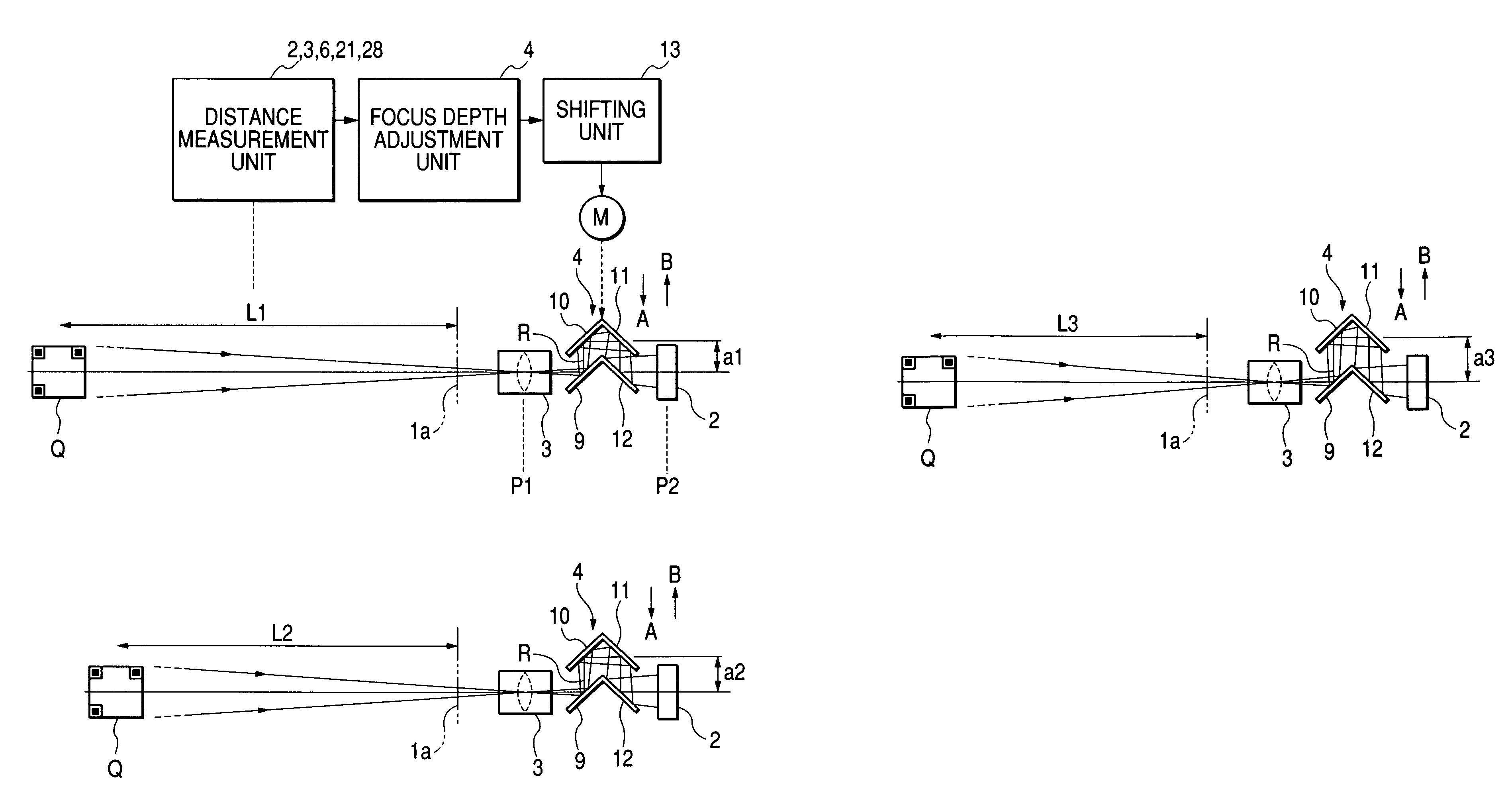
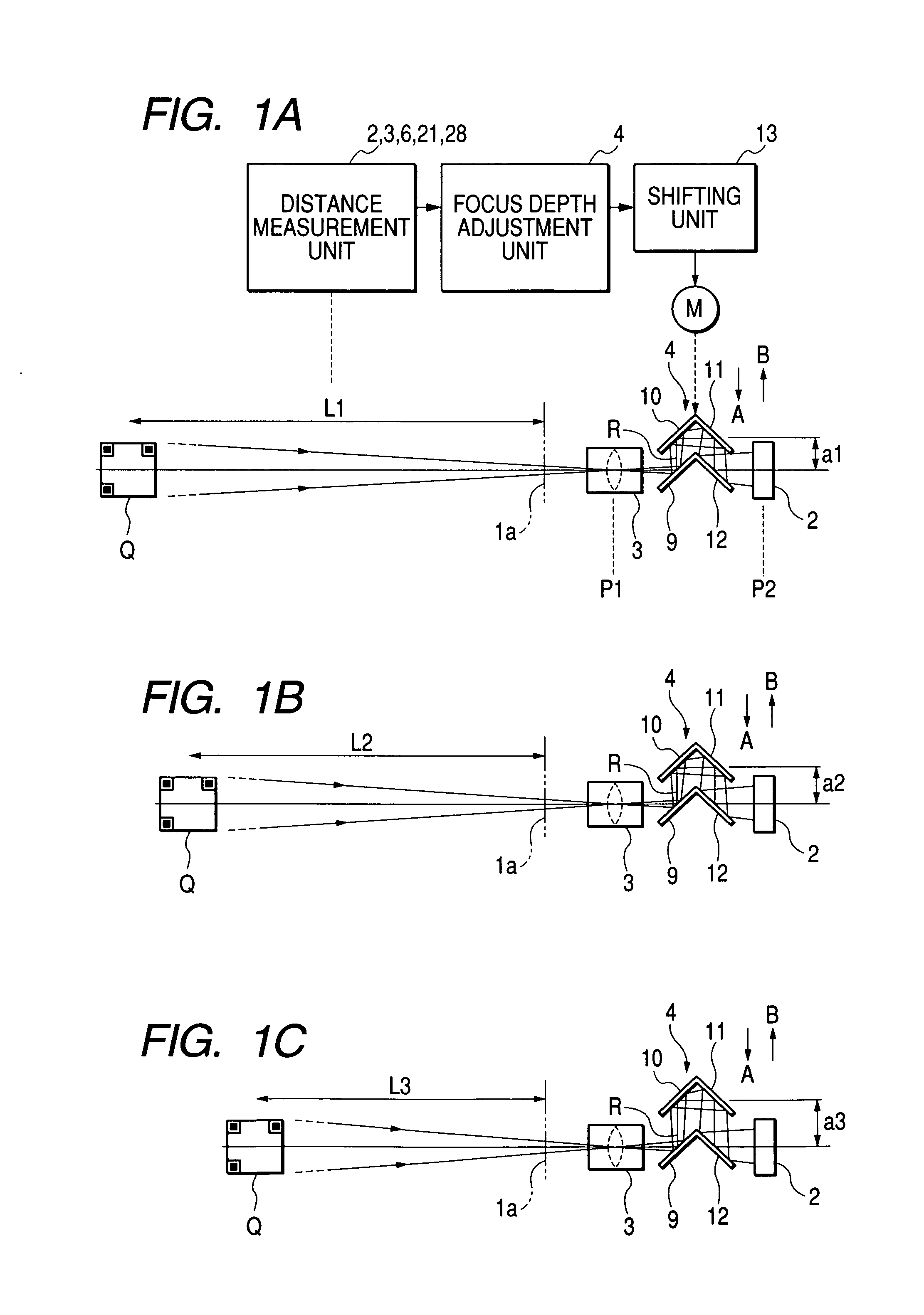
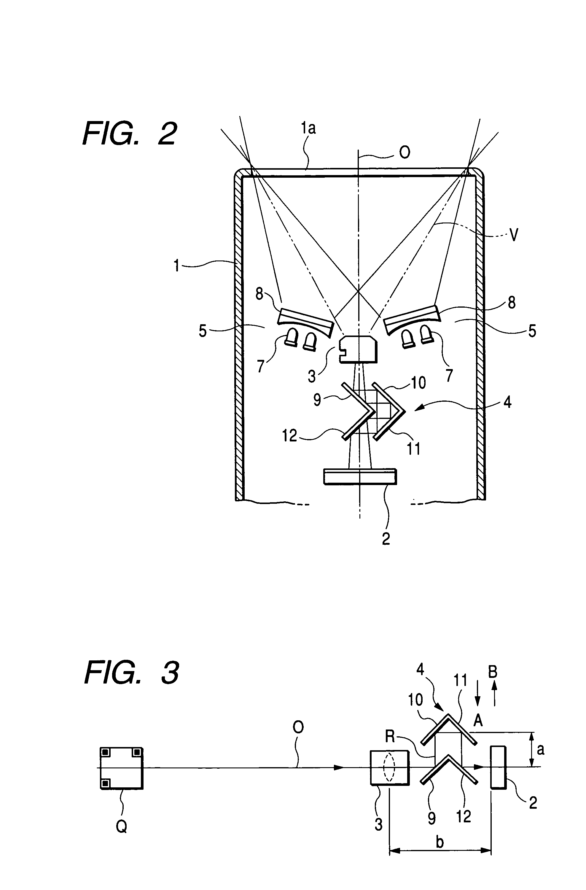
[0041]A first embodiment of the present invention will be explained referring to FIG. 1 and FIG. 6. A two-dimensional code reading apparatus, that is, an optical information reading apparatus of the first embodiment, has a main unit 1 which is a lengthwise shape and a size suitable for portability and operation with a single hand as partly shown in FIG. 2. As described later, the main unit 1 is equipped with an optical system (i.e., reading means) at the end of the main unit for reading the two-dimensional code Q (refer to FIG. 1 and FIG. 3.), for example, a QR code printed on an object from which optical information is read (hereinafter, referred to as “object”) such as a label P (refer to FIG. 5 and FIG. 6) mounted on commercial products. A rectangular transparent reading window 1a is formed at the end of the main unit 1.
[0042]The optical system includes an optical sensor 2, an image-forming lens 3, a focus depth adjustment unit 4 located between the optical sensor 2 and the image...
second embodiment
[0069]In the second embodiment, as shown in FIG. 7, a focus depth adjustment unit 30 as a light path bending means has, for example, four sets of reflection surfaces. One set of reflection surfaces bends a light path R two times by 90 degrees at each time, resulting in eight bendings of the light path R in total with the four sets of reflection surfaces. That is, the focus depth adjustment unit 30 has eight reflection mirrors from first to eight, that is, mirrors 31 to 38. A reflection light passed through the image-forming lens 3 is reflected by the first to eight reflection mirrors 31 to 38 by 90 degrees at each reflection mirror, and inputted into the optical sensor 2.
[0070]The first, the fourth, the fifth, and the eighth of the reflection mirrors 31, 34, 35, and 38 are bonded as a unit, and fixed in the main unit 1. On the other hand, the second, the third, the sixth, and the seventh reflection mirrors 32, 33, 36, and 37 are bonded as a unit, and shifted to directions A and B in...
third embodiment
[0071]In the third embodiment, as shown in FIG. 8, a focus depth adjustment unit 39 as a light path bending means has, for example, a set of reflection surfaces. The set of reflection surfaces bends a light path R two times by 90 degrees at each time. That is, the focus depth adjustment unit 39 has a first reflection mirror 40 and a second reflection mirror 41 bonded as a unit at right angles, and a shifting unit for shifting the first and the second reflection mirrors 40 and 41 back and forth (i.e., the directions C and D indicated by arrows).
[0072]The optical sensor 2 is arranged at side (i.e., at upper right position in FIG. 8) of the image-forming lens 3 facing backward. A reflection light passed through the image-forming lens 3 is inputted into the optical sensor 2 after bended by the first and the second reflection mirrors 40 and 41 by 90 degrees at each mirror. The light path length can be changed by displacing the first and the second reflection mirrors 40 and 41 to the dire...
PUM
 Abstract
Description
Claims
Application Information
 - R&D
- Intellectual Property
- Life Sciences
- Materials
- Tech Scout
- Unparalleled Data Quality
- Higher Quality Content
- 60% Fewer Hallucinations
Browse by: Latest US Patents, China's latest patents, Technical Efficacy Thesaurus, Application Domain, Technology Topic, Popular Technical Reports.
© 2025 PatSnap. All rights reserved.Legal|Privacy policy|Modern Slavery Act Transparency Statement|Sitemap|About US| Contact US: help@patsnap.com