Illuminator

a technology of illumination and reflector, which is applied in the field of illumination, can solve the problems of relatively low flux density of light, large etendue of illumination, and drawbacks of illumination, and achieve the effects of reducing manufacturing costs, simplifying a number of assembly steps, and reducing the etendue of light emitted

Inactive Publication Date: 2007-12-11
SAMSUNG ELECTRONICS CO LTD
View PDF10 Cites 61 Cited by
  • Summary
  • Abstract
  • Description
  • Claims
  • Application Information

AI Technical Summary

Benefits of technology

[0013]The present general inventive concept provides an illuminator which can reduce manufacturing costs, simplify a number of assembly steps, reduce etendue of light emitted from an LED and loss of the light simultaneously, and increase a flux density of the light.

Problems solved by technology

However, the illuminator also has drawbacks, such as a relatively large etendue and a relatively low flux density of light.
Otherwise, a loss of light is generated.
Also, since the tapered light pipe is needed, manufacturing costs are high.
Furthermore, a large number of assembly steps are required for the accurate arrangement of the light pipe.

Method used


Image

  • Illuminator
  • Illuminator
  • Illuminator

Examples


Embodiment Construction

[0030]Reference will now be made in detail to the embodiments of the present general inventive concept, examples of which are illustrated in the accompanying drawings, wherein like reference numerals refer to the like elements throughout. The embodiments are described below in order to explain the present general inventive concept while referring to the figures.

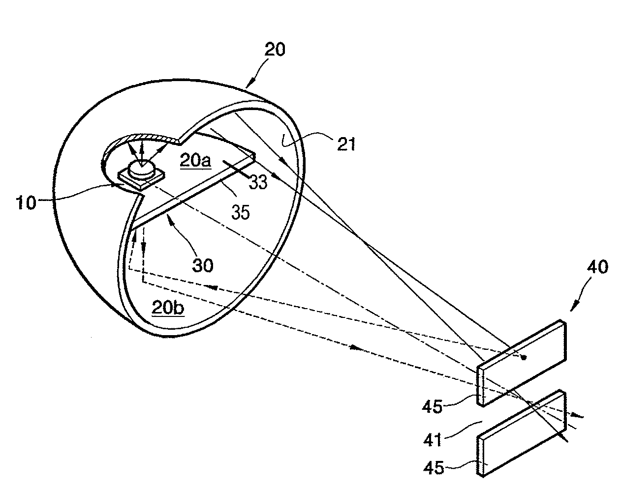
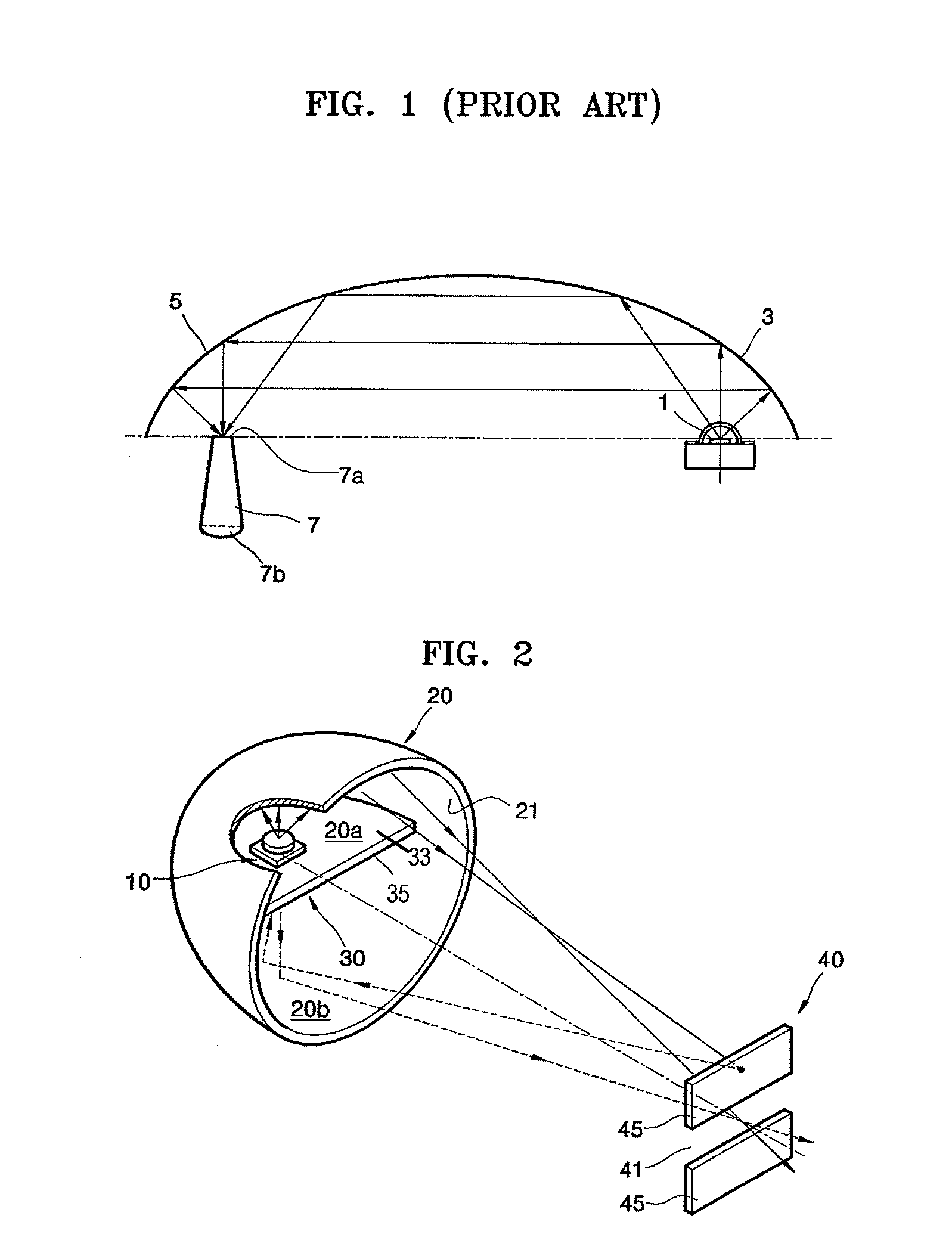
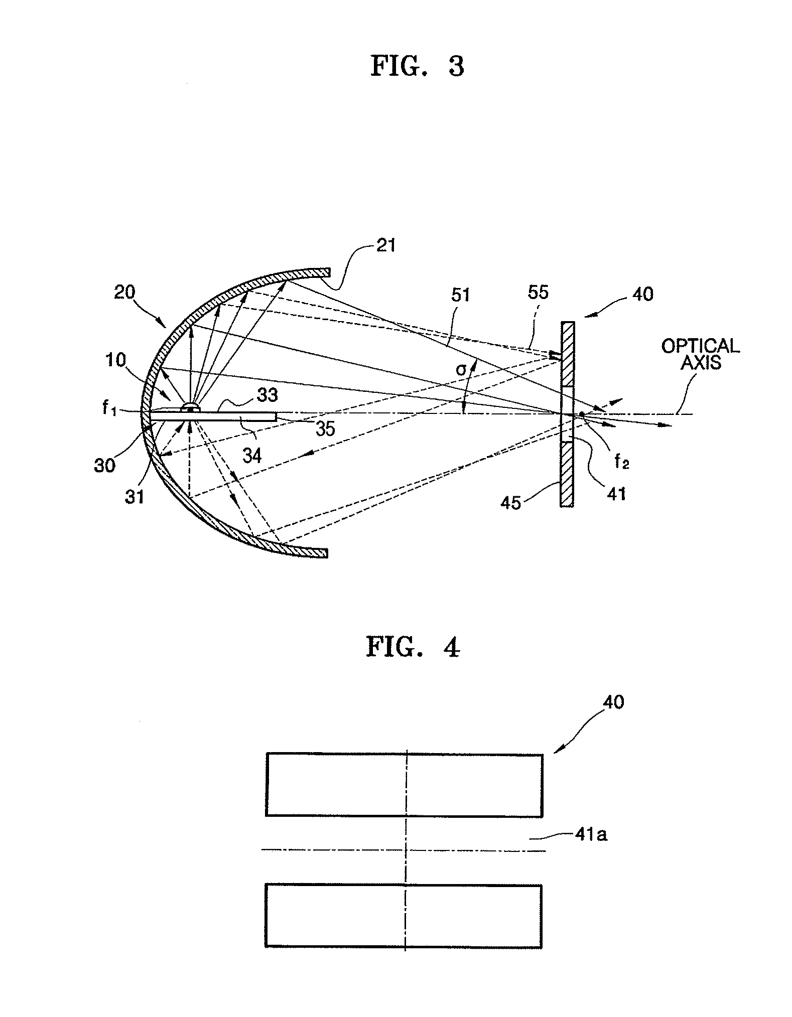
[0031]FIG. 2 is a perspective view illustrating an illuminator according to an embodiment of the present general inventive concept. FIG. 3 is a sectional view illustrating the illuminator of FIG. 2.

[0032]Referring to FIGS. 2 and 3, the illuminator includes a light source 10 to generate and emit light, a concave mirror 20 to reflect the light emitted from the light source 10 in a predetermined direction, an inner reflective mirror 30 provided on an optical axis of the concave mirror 20, and a retro-reflective mirror 40 arranged to face the concave mirror 20. The retro-reflective mirror 40 is provided on a proceeding path of th...


PUM


Abstract

An illuminator includes a concave mirror to reflect incident light in a predetermined direction, an inner reflective mirror provided on an optical axis of the concave mirror and having a reflective surface at least one surface thereof, a light source installed on at least one surface of the inner reflective mirror to generate and illuminate light, and a retro-reflective mirror provided at a focal point of the light reflected from the concave mirror, or in a vicinity of the focal point, and having an aperture through which some of the light illuminated from the light source and reflected by the concave mirror passes and a retro-reflective surface to reflect remaining light not passing through the aperture back toward the concave mirror.

Description

CROSS-REFERENCE TO RELATED APPLICATIONS[0001]This application claims the benefit under 35 U.S.C. § 119 of Korean Patent Application No. 2004-83541, filed on Oct. 19, 2004, in the Korean Intellectual Property Office, the disclosure of which is incorporated herein in its entirety by reference.BACKGROUND OF THE INVENTION[0002]1. Field of the Invention[0003]The present general inventive concept relates to an illuminator to illuminate light emitted from a light source in a direction, and more particularly, to an illuminator which can reduce etendue of light emitted from a light emitting diode (LED) and simultaneously increase a flux density of the light.[0004]2. Description of the Related Art[0005]In general, an illuminator generates light and concentrates the generated light in a direction. The illuminator is employed in a liquid crystal display (LCD) device which cannot emit light by itself, or in an image projecting apparatus which generates an image using an image forming device, suc...

Claims


Application Information

Patent Timeline
Patent Type & Authority Patents(United States)
IPC IPC(8): F21V7/00
CPCG02B5/12G03B21/2066G02B19/0023G02B19/0028G02B19/0061G03B21/2033H04N9/315F21V7/0025F21V11/08F21Y2101/02F21Y2115/10F21Y2107/90G02B27/00
Inventor SOKOLOV, KIRILLBORODOULINE, ALEXELLEE, YOUNG-CHOLLEE, WON-YONG
Owner SAMSUNG ELECTRONICS CO LTD
Why Eureka
Try Eureka